Continue to Site

Welcome to EDAboard.com

Welcome to our site! EDAboard.com is an international Electronics Discussion Forum focused on EDA software, circuits, schematics, books, theory, papers, asic, pld, 8051, DSP, Network, RF, Analog Design, PCB, Service Manuals... and a whole lot more! To participate you need to register. Registration is free. Click here to register now.

Frequency in different loops joined via transformer

Salvador12

Full Member level 4
Joined
Jul 16, 2014
Messages
206
Helped
3
Reputation
6
Reaction score
7
Trophy points
1,298
Activity points
3,950
So I have a curious question. I have a loop with two capacitors and two inductors. The first standalone inductor is a high frequency generating coil within this loop, the second inductor is a primary of a transformer. The capacitors are coupling capacitors.
my question is this, if the capacitors have low value then in order for me to be able to transfer any real current i need that current to be at a high frequency where the reactance of the capacitors is low (comparable to circuit resistance) and that is fine for me.
but what will happen once the primary coil with the transformer is introduced to the loop as shown in the attached picture, assuming the primary of the transformer can have the same impedance as the high frequency current generating coil on the left side ?

The idea is to have high frequency PWM current in the loop of the primary side of the transformer and then have low frequency AC on the secondary side of the transformer, where the transformer core and secondary winding with it's high inductance serves as the filter but the primary low inductance side coil together with the capacitors can have high frequency current in the loop. Is this possible or will the transformer even with a low inductance primary still choke the high frequency current in the primary loop given the primary of the transformer is in series with the loop?

Or maybe I need to attach the transformer primary parallel to the main loop creating a parallel LC instead of a series one as shown in the picture.

I appreciate your thoughts.
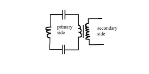
 

Attachments

  • konturs.png
    konturs.png
    11.8 KB · Views: 33
Hi,

You correctly said, you need high frequency.

but to get "high current" you need to have low impedance.
For the capacitors this is OK.

But what about the left coil? If it is acting like a signal generator, then draw it like a signal generator (you say PWM). Maybe with it´s behavioral serial and parallel impedances.

AND: what about the transformer? To get high current (AC) on the primary side, there needs to be high current on the secondary side, too.
A transformer isn´t just a coil. A transformer "reflects" the secodary current to the primary side and vice versa.

A transformer with open secondary side:
Has a rather huge impedance due to it´s rather huge inductance: it´s self inductance
Thus you can´t push high currents through an OPEN transformer.
But there is the coupling to the secondary. It is in parallel to the self inductance.
So if you want high current you need to "close" the secondary loop.
In extreme case you short circuit the secondary side.
Then you get a relatively small inductance: the coupling inductance, or leakage inductance.

****
So what you have drawn is not realistic. You need to investigate for more details.
(Signal generation side, as well as secondary transformer side, and all coil and transformer internals)

Klaus
 
No sources involved in the shown schematic. What is a "high frequency generating coil"? If it's part of a generator, why not symbolizing it by a source?
Secondly, how is the said low frequency signal generated? If you want the "HF" coil to source a PWM voltage (sum of PWM carrier and modulation signal), it must be designed as low frequency transformer with respective saturation flux.
 
I believe it's by experimentation we can explore what waveform comes from the secondary if you apply a rapidly switched similar waveform at the primary. We have combinations: a) inductor in series with primary vs secondary, and b) switching device in series with primary vs secondary. Four combinations in all. Four different methods to create Sine PWM.

I tried a simulation comparing all four simultaneously. All had a similar resistive load. No capacitors were included on either side of the transformer.
I remember one of the results looking as though it yielded smoother sine-like output than the other three.
 
You must learn the impedance formulae for XC(f) and XL(f) and the resonant frequencies and gain factor Q to appreciate the resonant low and high frequency effects. Inductors and transformers are rarely useful over bandwidth of 2 decades because all have non-ideal due to compromised in winding resistance, core saturation high voltage, mutual coupling factors, dense interwinding capacitance on primary and feedthru capacitance on secondary. The impedance changes must be realized with actual RLC values.

But I have simulated some ideal parts like your drawing with mouse modifiable values and sliders so you can try to figure out what is happening with a square wave FET switching current on and off. Since 2 caps are shown, only 1 is necessary to block DC and the effective value reduces with 2 in series.

The high voltage depends on RdsOn and the current peak when the switch opens after time interval T to generate V=LdI/dt with load resistance and capacitance affecting dt.

You may edit any value including Transformer N ratio set to 1 for now.
 
Last edited:
Hi,

You correctly said, you need high frequency.

but to get "high current" you need to have low impedance.
For the capacitors this is OK.

But what about the left coil? If it is acting like a signal generator, then draw it like a signal generator (you say PWM). Maybe with it´s behavioral serial and parallel impedances.

AND: what about the transformer? To get high current (AC) on the primary side, there needs to be high current on the secondary side, too.
A transformer isn´t just a coil. A transformer "reflects" the secodary current to the primary side and vice versa.

A transformer with open secondary side:
Has a rather huge impedance due to it´s rather huge inductance: it´s self inductance
Thus you can´t push high currents through an OPEN transformer.
But there is the coupling to the secondary. It is in parallel to the self inductance.
So if you want high current you need to "close" the secondary loop.
In extreme case you short circuit the secondary side.
Then you get a relatively small inductance: the coupling inductance, or leakage inductance.

****
So what you have drawn is not realistic. You need to investigate for more details.
(Signal generation side, as well as secondary transformer side, and all coil and transformer internals)

Klaus
Ok , pardon for not being full with all the details, I asked this as a more general question. But ok for you and everyone out there let me fill in some gaps.

The coil on the left is a generator coil, the transformer on the right , just assume it has low reactance loaded secondary, the transformer primary and generator coil are made to have almost equal inductances where the transformer primary inductance is made to match the generator coil inductance as the transformer load approaches it's maximum. At this moment I wonder , when the two inductances are almost equal , what happens frequency wise, assume the generator coil is capable of delivering the required current. Is there a difference in frequency between the primary side of the transformer and secondary side , given the primary side is driven with a PWM signal, I guess what I'm asking is can a transformer by itself work as a sort of filter where you can have high frequency PWM on one side and resulting low frequency AC in the load attached to the secondary or does there need to be a filter before the transformer primary?
 

LaTeX Commands Quick-Menu:

Part and Inventory Search

Welcome to EDABoard.com

Sponsor

Back
Top