NigthMoth
Member level 1

Dear all.
I was playing with broken air humidifier and, for self-education, decided to make “reverse engineering” of its power supply module: draw its circuit diagram, try to understand how it works in theory and compare my calculations with reality.
After three weeks of meditation on this circuit and explosion of this module when I tried to perform some tests on it, there is still a lot of points that I can’t understand. Now I’m trying to theoretically estimate “34V Out” waveform for this circuit and compare it with oscilloscope test.
My detailed questions to community below.
I tried to add as much as possible “reverse engineered” information to this post, hope it also can be intereset to community.
Circuit diagram:
Circuit elements datasheets:
Q1: JCS4N60 (N-CHANNEL MOSFET)
Q2: A1015 (Transistor PNP)
Q3: C1815 (Transistor NPN)
DW1, DW2: 18-2 (Zener) 17.5-18.3V
D6: HER203 (Rectifier diode)
D12: HER303 (Rectifier diode)
IC1: EL817 (Optocoupler)
IC2: TL431 (Shunt regulator)
IC3: LM78L05 (Voltage Regulator)
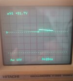
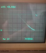
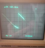
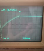
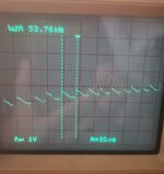
Oscilloscope test for “34V Out”: Vmin 31.7 V, Vmax 35.23 V, Ripple Vpp 3.53 V, Ripple rising time 0.964 mS, Ripple drop time 79.636 mS. "Subripples" on rising stage <1V, about 50kHz;
Here are my questions :
1) How one can theoretically estimate output ripple Vpp?
I made two attempts to calculate it, but my calculations lead to contradiction with oscilloscope data or to energy misbalance (?):
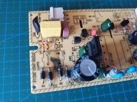
2) Why did this power module explode? And why epicenter is between cathode of D2 and LF2 Coil?
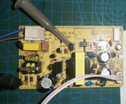
I tried to check waveforms on right side of C2. I connected oscilloscope probe tip between C2 and R2, and probe ground to D4’s anode (picture attached). After powering module on, master protective fuse in my house fired and switched off electricity in my house… Then I disconnected oscilloscope probe and tried to power-on this module again. This time it exploded with explosion epicenter between cathode of D2 and LF2 Coil.
I estimated that the voltage across these two points should not exceed ~25V induced voltage on Auxiliary coil and very little current because of R2, R1, R7, C2 in this loop, and it should be safe enough… but it looks like I missing some other point.
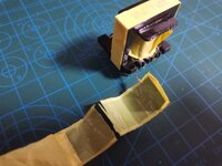
3) What is the purpose of a dark grey-thin film connected to Aux. coil between insulation tape in transformer?
There was about 5cm dark grey-thin film inside isolation tape wrapped between Primary and Auxiliary coils of transformer, and this film was connected to pin 1 of the transformer with wire. ?
I was playing with broken air humidifier and, for self-education, decided to make “reverse engineering” of its power supply module: draw its circuit diagram, try to understand how it works in theory and compare my calculations with reality.
After three weeks of meditation on this circuit and explosion of this module when I tried to perform some tests on it, there is still a lot of points that I can’t understand. Now I’m trying to theoretically estimate “34V Out” waveform for this circuit and compare it with oscilloscope test.
My detailed questions to community below.
I tried to add as much as possible “reverse engineered” information to this post, hope it also can be intereset to community.
Circuit diagram:
|
|
Circuit elements datasheets:
Q1: JCS4N60 (N-CHANNEL MOSFET)
Q2: A1015 (Transistor PNP)
Q3: C1815 (Transistor NPN)
DW1, DW2: 18-2 (Zener) 17.5-18.3V
D6: HER203 (Rectifier diode)
D12: HER303 (Rectifier diode)
IC1: EL817 (Optocoupler)
IC2: TL431 (Shunt regulator)
IC3: LM78L05 (Voltage Regulator)
Oscilloscope test for “34V Out”: Vmin 31.7 V, Vmax 35.23 V, Ripple Vpp 3.53 V, Ripple rising time 0.964 mS, Ripple drop time 79.636 mS. "Subripples" on rising stage <1V, about 50kHz;
|
Here are my questions :
1) How one can theoretically estimate output ripple Vpp?
I made two attempts to calculate it, but my calculations lead to contradiction with oscilloscope data or to energy misbalance (?):
- Attempt #1 Estimated 0.17 Vpp - far below 3.53 Vpp measured with oscilloscope
Attempt #1 (“Adding ΔE to already stored energy and calculating new voltages”)
Let’s say this power supply unit was powered-on some time ago.
Total voltage that already exists across EC3 and EC4 (“34V Output”) is threshold voltage settled by shunt regulator and voltage divider, VTH = 34.42 V.
Taking into account 15:7 winding ratio across EC3 and EC4 and formula E = 0.5*C*V^2,
EC3 already charged to VEC3Th = 23.47 V and store EEC3Th = 90889 μJ of energy,
EC4 already charged to VEC4Th = 10.95 V and store EEC4Th = 28177 μJ of energy.
On next cycle, secondary coils receive ΔE = 1122 μJ of energy in total.
EC3 receives ΔEEC3 = 765 μJ and EC4 receives ΔEEC4 = 357 μJ (Assuming energy distribution ratio the same as 15:7 winding ratio across EC3 and EC4).
New energy values on EC3 and EC4 is peak values:
EC3: EEC3PK = EEC3Th + ΔEEC3 = 90889 μJ + 765 μJ = 91654 μJ, so peak voltage VEC3PK = 23.57 V;
EC4: EEC4PK = EEC4Th + ΔEEC4 = 28177 μJ + 357 μJ = 28534 μJ, so peak voltage VEC4PK = 11.02 V;
New “34V Output” voltage is peak voltage VPK = VEC3PK + VEC4PK = 23.57 V + 11.02 V = 34.59 V;
Ripple peak to peak voltage is Vpp = VPK - VTH = 34.59 V - 34.42 V = 0.17 V
Far below 3.53 V measured with oscilloscope!
- Attempt #2 Estimated 3.38 Vpp - almost as 3.53 Vpp measured with oscilloscope, but it looks like capacitors receiving more energy than it is supplied by coil. Is my attempt #2 somehow correct, or it’s just “drawing the bullseye after firing”?
Attempt #2. (“Adding ΔV calculated from ΔE directly to capacitors”)
Let’s say this power supply unit was powered-on some time ago.
Total voltage that already exists across EC3 and EC4 (“34V Output”) is threshold voltage settled by shunt regulator and voltage divider, VTH = 34.42 V.
Taking into account 15:7 winding ratio across EC3 and EC4 and formula E = 0.5*C*V^2,
EC3 already charged to VEC3Th = 23.47 V and store EEC3Th = 90889 μJ of energy,
EC4 already charged to VEC4Th = 10.95 V and store EEC4Th = 28177 μJ of energy.
On next cycle, secondary coils receive ΔE = 1122 μJ of energy in total.
EC3 receives ΔEEC3 = 765 μJ and EC4 receives ΔEEC4 = 357 μJ (Assuming energy distribution ratio the same as 15:7 winding ratio across EC3 and EC4).
Now I’m assuming that received ΔE adds ΔV to capacitors as if there is no any previously existing voltage across EC3 and EC4 according to V = (2*E/C)^0.5
EC3: ΔVEC3 = (2*ΔEEC3/CEC3)^0.5 = (2*765μJ/330μF)^0.5 = 2.15 V, so peak voltage VEC3PK = 25.62 V;
EC4: ΔVEC4 = (2*ΔEEC4/CEC4)^0.5 = (2*357μJ/470μF)&0.5 = 1.23 V, so peak voltage VEC4PK = 12.18 V;
New “34V Output” voltage VPK = 25.62V + 12.18V = 37.8 V;
Ripple peak to peak voltage Vpp = 2.15V + 1.23V = 3.38 V;
Almost as 3.53 V measured with oscilloscope!
But now, from E = 0.5*C*V^2, energy stored in EC3 is EEC3PK = 108303 μJ, and in EC4 is EEC3PK = 34863 μJ, or 143166 μJ in total for two capacitors. So it looks like it has been added 24100 μJ of energy (143166 μJ - 90889 μJ - 28177 μJ). But secondary coil supplied only 1122 μJ.
Calculation of ΔE = 1122 μJ:
Threshold current in primary coil (controlled by Q3)
VBE(Q3) = IPTh*R6
IPTh = VBE(Q3)/R6 = 0.7V/0.47Ω = 1.5 A
Energy stored in magnetic field for threshold current:
ΔE = 0.5*LP* IPTh^2 = 0.5*997μF*(1.5A)^2= 1122 μJ
Calculation of threshold voltage VTH = 34.42 V for “34V Output”:VR11 = VRef(IC2) = VTH*R11/(R14+R11)
VTH = VRef(IC2)*(R14 + R11)/R11 = 2.495V*(49.9kΩ + 3.9kΩ)/3.9kΩ = 34.42 V
2) Why did this power module explode? And why epicenter is between cathode of D2 and LF2 Coil?
I tried to check waveforms on right side of C2. I connected oscilloscope probe tip between C2 and R2, and probe ground to D4’s anode (picture attached). After powering module on, master protective fuse in my house fired and switched off electricity in my house… Then I disconnected oscilloscope probe and tried to power-on this module again. This time it exploded with explosion epicenter between cathode of D2 and LF2 Coil.
I estimated that the voltage across these two points should not exceed ~25V induced voltage on Auxiliary coil and very little current because of R2, R1, R7, C2 in this loop, and it should be safe enough… but it looks like I missing some other point.
3) What is the purpose of a dark grey-thin film connected to Aux. coil between insulation tape in transformer?
There was about 5cm dark grey-thin film inside isolation tape wrapped between Primary and Auxiliary coils of transformer, and this film was connected to pin 1 of the transformer with wire. ?
