Continue to Site

Welcome to EDAboard.com

Welcome to our site! EDAboard.com is an international Electronics Discussion Forum focused on EDA software, circuits, schematics, books, theory, papers, asic, pld, 8051, DSP, Network, RF, Analog Design, PCB, Service Manuals... and a whole lot more! To participate you need to register. Registration is free. Click here to register now.

Fix an rc toy car mainboard power transistors

Status
Not open for further replies.
The new transistors are better than the original transistors and will survive the higher battery voltage and current.
BUT their case is different and they might not fit.
 

hFE is still low

maybe no choice except to buy a good number of them[or the TIP models previously posted], and select the ones with the highest hFE

often the hFE of the actual devices will be [a fair bit] higher than the min figure given in the data-sheets, so you could get lucky
 

How do they compare? Are the numbers given calculated the same way and same rate?
 

How do they compare? Are the numbers given calculated the same way and same rate?
You can look up the numbers like anyone else.
The new transistors have double the maximum allowed current (10A) and 5 times the maximum allowed heating with a heatsink (50W).
BUT they might not fit.
 

Thank you,

I did look at the datasheets but I dont get the hfe.. Those transistors only show a minimum hfe and no maximum or the curb only shows a little bit more then 100 for hfe and the 2SC3420 showed 600?? Can someone please explain I don,t get it I am a total noob..
 

You need to know the minimum hFE at your maximum current. When the current is low then the hFE is usually higher.
Each transistor part number has a range of hFE numbers, some of the transistors are better that some of the others. You cannot order only the best ones, you get whatever they have.
 

as previously posted, hFE is a measure of gain or amplification. the higher the hFE the higher the gain
BUT
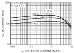
hFE varies [amongst other things] by the current passing through the transistor, the higher the current, the lower the gain

http://tymkrs.tumblr.com/post/13115454729/beta-hfe-gain-2n3904s-i-think-its-transistor
http://www.brighthubengineering.com...17851-forward-current-gain-in-bjts-explained/
**broken link removed**
http://educypedia.karadimov.info/library/2 Transistor-Thyristor.pdf

hfr.gif

Look at the top curve [125 C]. hFE is nearly 200 but as Ic [current through the transistor] starts to exceed 2A the gain starts to fall, going down to just 60 at 10A

If the gain is too low, then the power can not be [fully] delivered to the motor.

So you have to find a transistor that can handle the higher current, higher wattage, same case or package, and have higher gain.
 
Last edited:

Ok then as this for a lipo battery that would generate a lot of amps not sure how this transistor would handle the situation.. Ihave searcged for a while and simply I think that there are no such through pins transistors to have all the right characteristics, I will probbably try to just replace those burnt transistors standard stuff and run the 9.6v pack hoping still that nothing else has been damaged.
 

Ok then as this for a lipo battery that would generate a lot of amps not sure how this transistor would handle the situation.. Ihave searcged for a while and simply I think that there are no such through pins transistors to have all the right characteristics, I will probbably try to just replace those burnt transistors standard stuff and run the 9.6v pack hoping still that nothing else has been damaged.
A Chinese Li-Po battery from Hobby King has almost no Amps but their batteries cost very little.

A battery does not force current, the motor takes only as much current as it needs. With the Ni-Cad battery then the 5A transistors survived so with 9.6V from a Li-Po battery then 10A transistors will easily survive. The original Oriental transistors are old and might not be available anymore.
 

Thanks, makes sense. I found those old transistors here and there but I think I will go with those 10 amps. Also do you know what amps I should look at when it comes to the 380 brushed motor? Is it the stall amps draw or maximum efficiency amps for example the Mabuchi RS 380 PH that would make sense in a 10V application.
 

When a DC motor starts running at maximum power its current is the stalled amount. It is stalled when it has maximum power but something prevents it from turning.

There are two Mabuchi RS 380 PH motors shown on its datasheet (found in Google), a 6V one and a 12V one. The 12V one draws a 14A stalled current so with 10V it will draw 10/12 x 14= 11.7A. I think the original 5A transistors will not be reliable.
 

Ok then it might be another motor as the original transistors lived well for close to 10 years using the standard 9.6V pack. I wanted to order those new transistors and it seems like a plag...Shipping prices are insane!!! Will need to see where I can can some locally.
 

Looking backtothis circuit board I toticed that the particular transistor that smelled burn is soldered to a 5W rectangular ceramic resistor, would that be possible that the resistor burnt and not the transistor and why one of the 4 transistors is soldered to a resistor?? I know I should post pics, still unsuccessfully.
 

Any ideas guys? I will anyway desolder this resistance and test it hopefully it got the first hit and saved the transistors..
 

Usually a resistor that been fried has obvious signs; charring, discoloration, blackening, or even pieces missing.
 

That's the thing... all the circuit board looks in perfect shape.. The base resistor is the same kind as those ones https://www.google.ca/search?q=5w+c...ay.com%2Fbhp%2F50-watt-power-resistor;225;225

Why is this resistor soldered to only one of the 3 pins or one of the 4 transistors?? Also by what I am reading the role of a base resistor is to protect the transistors from getting to much power so the logical of my situation would be that it should have saved the transistors no? But then why would I only be left with rear motion and no more forward??
 

The output transistors are probably used as on-off switches. Base current turns them on and no base current turns them off.
If the load draws too much current then the transistor is not turned on hard enough which makes it too hot. Heating is the current in the transistor times the voltage across it so if it is turned on very well then it has a low voltage across it which produces less heating.

You used a battery voltage that is too high which caused the current in the motor to be too high.
You cannot simply reduce the value of the base resistors to turn on the transistors harder because the transistors already might have their maximum allowed base current or the driver transistors that supply this base current might already be operating at their maximum allowed current.
 

Thank you,

Wow, this is complicated..! So if something has fried it is more likely the forward motion power transistors then this base resistor right?
 

Status
Not open for further replies.

Part and Inventory Search

Welcome to EDABoard.com

Sponsor

Back
Top