sutapanaki
Advanced Member level 4
Pretty immediate in this case. The output resistance with feedback removed is R1, the loop gain with port (terminals of RL) shorted is A and the loop gain with port open is 0. The result is R1*(1+A).
Follow along with the video below to see how to install our site as a web app on your home screen.
Note: This feature may not be available in some browsers.
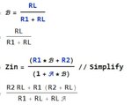
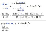
Good day everyone! I need your help on this one. I'd like to derive the equation for the closed-loop input impedance of the circuit attached. The final form of the equation is also shown below.
View attachment 157314
View attachment 157313
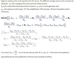
Here's what I have tried
View attachment 157316
I was stuck. Can you tell what other route I can take to go about this derivation? Thanks!
With a current for its input then its input voltage barely changes. Then its input impedance at low frequencies is extremely low (a virtual ground).
Hi,
I agree with audioguru.
The voltage will be almost zero.
But yes, even if small it will be proportional to input current.
Klaus
Sorry, I don't understand these last posts. It has been already proven that Zin = R2/(1+A*B) that means Zin decreases as A increases.
Amplification does not increase. The opamp already has a gain of almost infinity for a modern opamp. But some old opamps do not have much gain. Aren't you talking about modern opamps?
The input signal is a very high impedance current source and it is feeding the extremely low input impedance of the opamp inverting input. Then the input signal voltage is so low that we say it is zero.
I don't know where the formula Zin = R2/(1+A*B) comes from, or what the definition of A and B are. However, both calculations of The Electrician and myself agree on what Zin is. Yes, Zin approaches zero as the op amp amplification approaches infinity. What don't you understand about my derivation of the nodal equations of the circuit?
Ratch
Ratch
Please have a look to #9. The formula was derived there.
You analysis is perfectly clear. Is just another approach to reach the solution.
Except that the value of the solution does not agree with what 3 other members have come up with.
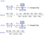
View attachment 157377
Ratch
Except that the value of the solution does not agree with what 3 other members have come up with.
View attachment 157377
Ratch
Well, it is very easy to verify. Just build a simulation schematic with ideal vcvs for the amplifier, put a large gain, look for the input impedance and check the expressions against simulation. Takes no more than 5 minutes.