Continue to Site

Welcome to EDAboard.com

Welcome to our site! EDAboard.com is an international Electronics Discussion Forum focused on EDA software, circuits, schematics, books, theory, papers, asic, pld, 8051, DSP, Network, RF, Analog Design, PCB, Service Manuals... and a whole lot more! To participate you need to register. Registration is free. Click here to register now.

Feedback on LED cube circuit sought

Status
Not open for further replies.
Hi,

And I have experimented with TLC4950 on my bread board. If you apply 12V to a single led attached to one of the channels then the TLC4590 can't completely shut off the LED. It's logic circuit runs of 5V and can only apply 5V to the channels. Same principal as trying to turn off a PNP transistor with the voltage applied to the base less that the voltage applied to the emitter.

It´s not a problem of the TLC4950, it´s a problem of your circuit that it can´t shut down the LEDs completely.
--> The TLC4950 is designed to properly work with up to 17V LED voltage. And it can drive up to 120mA. Enough to supply 8 LEDs with 15mA each.
You overcomplicate the circuit. Causing much trouble.
Calculate the reisitors for 15mA at 3,9V (across LED and resistor). Supply the whole circuit with 5V and you are done.
No need for 12V, no need for an extra voltage regulation circuit, no need for extra BJTs, reduced heat. Where is a drawback?
This causes about 2W per IC of power dissipation. Thus I recommend a proper thermal PCB layout and additionally I´d glue a heatsink onto each driver IC.

Klaus
 

Hi,


It´s not a problem of the TLC4950, it´s a problem of your circuit that it can´t shut down the LEDs completely.
--> The TLC4950 is designed to properly work with up to 17V LED voltage. And it can drive up to 120mA. Enough to supply 8 LEDs with 15mA each.
You overcomplicate the circuit. Causing much trouble.
Calculate the reisitors for 15mA at 3,9V (across LED and resistor). Supply the whole circuit with 5V and you are done.
No need for 12V, no need for an extra voltage regulation circuit, no need for extra BJTs, reduced heat. Where is a drawback?
This causes about 2W per IC of power dissipation. Thus I recommend a proper thermal PCB layout and additionally I´d glue a heatsink onto each driver IC.

Klaus
I can't avoid the transistors driven by the MCP23017. This IC is capable of only 15mA per channel (source or sink), or there abouts, and it is incapable of driving 8 x common anode RGB LEDs by itself at a max of 400mA or so.

And I can't avoid the MCP23017 because there are not enough pins on an Arduino Mega to control 64 x 8 x common anode RGB LEDs plus the TLC4950s.

And even if there were enough pins they can only source or sink 25mA or so, where I require a max of around 400mA, so I can't avoid the transistors.

Nor can I avoid the transistors on the TLC4950 channels. 8 x RGB blue at 18mA = 144mA. The TLC4950 can sink a max of 120mA per channel.

I simply can't see any other way of doing it other than what I have designed.

Agree it would have been better to calculate my resistors for 4V rather than 5V but it is too late - I have already bought the resistors and soldered together the first 8 columns so I am committed.

If I can't find a power source that can deliver around 7V at 30A or so then I have no other choice than to use the LM317s with 12V from the ATX PSU.
 

Hi,

Did you test the proper function of the BC373 in combination with the MCP23017, current limiting resistors for 5V and your low side driving circuit?
If not, then do it.

Klaus
 

So far I have tested a BC516 supplying 8 x common anode RGB LEDs recently. But will repeat with a BC337 now that I know I can get away with those. BC337 in saturation and biased for max current is still close to the limit of the MC23017.

Since I am using LM317 to supply about 7V then I could afford to keep the BC516s and not drive the MCP23017 close to their limit.

I am intending to do a test with the MCP23017 and LM317 added and with BC327 on the RGB cathodes manually controlled with some jumper wires.
 

Hi,

I can´t see how it can work the way you want. But on the other hand it seems you don´t want to hear this.
I´ve tried my best to save your time.

Now all I can do is to whish you good success with your project.

Klaus
 

Why do you believe a MCP23107 channel would not be able to drive a BC337 or BC516?

And what would you suggest as an alternative?

At least on ebay it is either a MCP23017 or a variety of other shift registers, all with much the same source/sink limitiations
 

Hi,

please use a simulation tool, or use a pencil, paper and (mostly) ohm´s law.
I already spent a lot of time. But it´s not my project.

If you come back with your calculations and found out that it does work, then I will be here to find the mistake.

Klaus
 

Actually, since I have soldered the first row of 8 columns of RGB LEDs, I can test the LM317, MCP23017, BC519 and BC327 on the real thing.
 

Hi,

please use a simulation tool, or use a pencil, paper and (mostly) ohm´s law.
I already spent a lot of time. But it´s not my project.

If you come back with your calculations and found out that it does work, then I will be here to find the mistake.

Klaus

I just started setting up a test circuit on my bread board and spotted one mistake I made.

I can't use BC516 or BC337 because they can only be emitter followers which means my LM317 will have no effect in raising the voltage.

I have to use BC517 or BC327.

- - - Updated - - -

No BC516 or BC517 in multisim so I have used TIP115 in place of BC517 for simulation.

And my design seems to work as expected without the ICs at least.

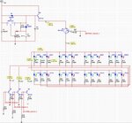
LEDCube.jpg
 

See, you have already tied the base BC516 or BC517 to the ground. The transistor cannot work if you tie the base to the ground.

The output channels in the LED drivers are constant current sources - you need to lift the base of the driving transistor from the ground and apply suitable voltage so that some reasonable current goes in the base that can turn on the transistor hard.

I am not sure how your circuit is going to work at all.

It works at this level at least.

And the bases of the BC327s are not going to be connected to GND in real life, rather they will be connected directly to the TLC4950 channels.

I have tied them to GND in Multisim simply to make the simulation run - there is no TLC4950 available to simulate.
Perhaps if I came up with a transistor based constant sink current source as a stand in for a TCL4950 channel.

attachment.php
 
Last edited:

Hi,

It works at this level at least.
Because your simulation is not realistc.

I don´t want to repeat the issue with the constant current driver outputs of the TLC4950...

Connecting Q1, Q3 and Q4 to the TLC4950 will result in increased emitter voltage of those transistors.
Thus you need higher voltage at the LEDS (referenced to GND)
and thus you need higher voltage at emitter of Q2
As soon as this voltage exceeds about 6.1V you may get in trouble with your Q5 circuit.

Additionally Q2 will become hot. Thus V_BE will decrease.. the output voltage referenced to GND will increase...

****
Nor can I avoid the transistors on the TLC4950 channels. 8 x RGB blue at 18mA = 144mA. The TLC4950 can sink a max of 120mA per channel.
Use two LEDs. Run one LED with 15mA and the other with 18mA.
How big is the difference in brightness. Maybe you can see a difference when they are next to each other, but are you able to see the difference when they are 10 cm apart?

And did you do a current measurement of the LEDs in your complete circuit when you expect it to be 18mA.

Klaus
 

Hi,


Because your simulation is not realistc.

I don´t want to repeat the issue with the constant current driver outputs of the TLC4950...

Connecting Q1, Q3 and Q4 to the TLC4950 will result in increased emitter voltage of those transistors.
Thus you need higher voltage at the LEDS (referenced to GND)
and thus you need higher voltage at emitter of Q2
As soon as this voltage exceeds about 6.1V you may get in trouble with your Q5 circuit.

Additionally Q2 will become hot. Thus V_BE will decrease.. the output voltage referenced to GND will increase...

****

Use two LEDs. Run one LED with 15mA and the other with 18mA.
How big is the difference in brightness. Maybe you can see a difference when they are next to each other, but are you able to see the difference when they are 10 cm apart?

And did you do a current measurement of the LEDs in your complete circuit when you expect it to be 18mA.

Klaus

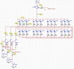
What if I was to do the following? 23R is my best guess from the datasheet what the impedance is of the TLC4950 output pins.

And Q2 in hindsight does not need to be a darlington so I changed it to TIP31.

But I also realised I might be better of making that LM317 circuit a regular high current LM317 straight from the data sheet, which would give me access to the full range of the 12V input.


LEDCube.jpg
 

Brililant, I just found these on ebay: **broken link removed**

Up until now I have only ever seen fixed voltage versions.

These are vastly more convenient than dicking around with high current LM317 circuits.
 

Hi,

23R is my best guess from the datasheet what the impedance is of the TLC4950 output pins.
Why guessing?
--> the datasheet tells you it is a "current source".
in post#11 I told you this.
in post #15 and #30 c_mitra told you the same.

Hard to help, if you ignore this all.

And Q2 in hindsight does not need to be a darlington so I changed it to TIP31.
This makes the voltage problem of Q2 emitter even worse.

Hard to help if you don´t do a simulation on your own.


But I also realised I might be better of making that LM317 circuit a regular high current LM317 straight from the data sheet, which would give me access to the full range of the 12V input.
I already told you that higher voltage increases the problem with Q2.
in post#21 I recommended to omit the complete voltage regulation circuit.

Hard to help if you ignore this.

Don´t get me wrong. You are free to design your circuit as you like.
But I ask myself why you ask for help but ignore all the recommendations and informations we give.

I see no progress, neither with the discussion, nor with your application.

Klaus
 

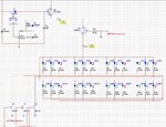
With the complication of the high current LM317 circuit removed and assuming a power supply that I can adjust the voltage to exactly what I need.

This seems to work OK in the simulator.

Any problems that I am not seeing apart from the fact that TLC4950 not in the simulation?

Just trying to come up with something workable I can try on my breadboard.

LEDCube.jpg

- - - Updated - - -

Hi,


Why guessing?
--> the datasheet tells you it is a "current source".
in post#11 I told you this.
in post #15 and #30 c_mitra told you the same.

Hard to help, if you ignore this all.


This makes the voltage problem of Q2 emitter even worse.

Hard to help if you don´t do a simulation on your own.


I already told you that higher voltage increases the problem with Q2.
in post#21 I recommended to omit the complete voltage regulation circuit.

Hard to help if you ignore this.

Don´t get me wrong. You are free to design your circuit as you like.
But I ask myself why you ask for help but ignore all the recommendations and informations we give.

I see no progress, neither with the discussion, nor with your application.

Klaus

Never mind about my guess of 23R I realized soon after posting that that you set the impedance of TLC5940 to what ever you want through the Iref resistor.

I have deleted the voltage regulation circuit because I found adjustable LED power supplies on ebay for $50 or so - I would much rather do things the easy way if I have a choice believe me.

And I am not ignoring you so much as not having my head around what you are telling me....trying to nut it out as I fiddle around with the simulated circuit.

I will have to use a stock standard LM317 circuit on my bread board though as an adjustable power supply stand in. Should be able to get away with testing 8 x 1 RGB colour at a time at least.
 
Last edited:

Status
Not open for further replies.

Part and Inventory Search

Welcome to EDABoard.com

Sponsor

Back
Top