Continue to Site

Welcome to EDAboard.com

Welcome to our site! EDAboard.com is an international Electronics Discussion Forum focused on EDA software, circuits, schematics, books, theory, papers, asic, pld, 8051, DSP, Network, RF, Analog Design, PCB, Service Manuals... and a whole lot more! To participate you need to register. Registration is free. Click here to register now.

Explanation of AC analysis of oscillator

miki1221

Newbie level 5
Newbie level 5
Joined
Aug 31, 2024
Messages
9
Helped
0
Reputation
0
Reaction score
0
Trophy points
1
Activity points
69
Can someone explain how we do a AC analysis of harmonic oscillator on following example.
I've done the the 16 Mhz oscillator, and simulated it, but I'm trying to understand how it is really working.
zad.png


The equivalent circuit is over here(hope so)
457349066_10233406753181310_6158822657399137013_n.jpg


So my question is, when I start to analyse by hand on paper, I find problem almost on every step, actually I'm not sure if I'm doing it right, so can someone help me go trough it.
I'm very interested in undarstanding of these and simmilar oscillators so, for you maybe this is quite simple, but I'm new in this so everything seems very complicated for me.
I'll be very appreciate if someone finds time to check and answer my question.
Here are results of DC analysis:
1. Ključni elementi kruga:

  • Ucc: 5 V
  • Transistor (Q1): S3018 (NPN)
    • R2=100 kΩ
    • R3=100 kΩ
    • R4=1 kΩ
    • R5=1 kΩ
    • R6=100Ω
    • C16=4.7 nF
    • C15=33pF
    • C15=33pF
  • Kristal:
    • XTAL1=16 MHz
2. (S3018):

  • HFE (β): 200


Ub=2,5V
Rb=50kΩ
UE=1,8V
IE=1,8mA=IC
UC=3,2V
UCE=1,4V

 
Solution
Hello all

After several iterations (building transistor AC model, merging transistor amplifier i/o impedances with impedances of other circuit components, etc) I ended up with below oscillator AC model.
I recognise that it is Pierce crystal oscillator.
For analysis of crystal operation I used this technical note.

Analysis_Pic3a.png


Most challenging for me is to prove phase shift in feedback loop.
Desired phase shift at second (B2) voltage divider is -105deg,
but when I calculate crystal impedance @16MHz and put it into voltage divider equation,
phase shift I got was about -120deg

I used math solver to check possible values of the crystal impedance (and B2 voltage divider gain and phase shift) between the crystal's serial and...
The rise time of a sine wave will be amplified by the excess inverting gain above the inverting losses. I expect Av is Rc/Rbe and perhaps as much as 40 dB while the filter loss to be low at -180 deg. An accurate model and Bode plot or simulation will prove this.

The crystal will have an equivalent cct. Of a parallel RLC cct with a fF series motion and very large || mH then a small parallel tuning cap in pF lowered by two parallel external caps specified by the cut for 25’C This is what you are missing.
 
Last edited:
The rise time of a sine wave will be amplified by the excess inverting above the inverting losses.
I expect Av is Rc/Rbe and perhaps as much as 40 dB while the filter loss to be low at -180 deg.
An accurate model and Bode plot or simulation will prove this.
Tried, but not wokring

1725148266310.png
 
I'm very interested in undarstanding of these and simmilar oscillators
Short explanation: An oscillator circuit provides a kick (to the bias of the transistor) at just the proper time during a cycle, thus keeping oscillations going. The kick is taken from the very network which is oscillating. The entire balance is often delicate, needing adjustments of component values, supply voltage, L:C ratio, etc.
 
When you read this then maybe you will understand. https://www.ti.com/lit/an/slaa322d/slaa322d.pdf?ts=1725153955012

Keep in mind 32 kHz Xtals (crystals) are cut and result in a parabolic (2nd order) temperature curve while most every other common Xtal at higher frequency is an AT cut with a 3rd order temperature curve.
--- Updated ---

Tried, but not wokring
Why would you feed 20MHz Vac 5Vpeak instead of 5Vdc for a 15 MHz crystal oscillator?

That makes no sense at all.
 
Last edited:
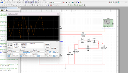
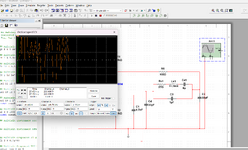
Your simulation setup is transient rather than AC analysis and not measuring loop gain. For exact analysis of loop gain considering source and loop impedances, you'll use Middlebrook's method, quite often discussed in the forum.
 
If you want an AC analysis, forcing a proper operating
point is key. The oscillator has one infinitesmal operating
point that satisfies DC. You will not hit it, by luck (except
when you think you are done and start doing hundred-
iteration MC loops, than "stuck mid-swing" results will
appear in time to ruin your weekend).

You could / should break the loop at an advantageous point
so that you have an "in" and an "out" to get a transfer
function.

Designing and simulating oscillators (esp. with the concerns
about XTAL modeling and the ability of simulator error tolerance
to outweigh / quench circuit activity, thereabouts) is an art all its
own, and I have the half-eaten box of crayons to prove it.
 
The phase characteristics of this 3rd order Xtal are key to determining the parallel then the series resonant frequency.

Below I tuned L of this Xtal model to create 15 MHz

The AT-cut crystals have a high Q above 10k which takes more than this number of cycles to reach full-swing stabilization.

The interesting thing about Xtals is the low power ratings in uW which seems unreal until we see how high the voltage exists internally with the motional capacitance in femptofarads reaching thousands of volts pp.


1725222113188.png
.
 
Last edited:
For Middlebrook and similar loopgain measurement methods, you can review LTspice examples LTspiceXVII\examples\Educational loopgain.asc and loopgain2.asc.

Here's an adaption of loopgain2 for the oscillator problem, using the crystal parameters by Toni:

1725269150014.png
 

Attachments

  • LoopGain_Osc.zip
    2.1 KB · Views: 20
In osciloskop ground? But here on picture it is not connected, the wire goes over.
Do you think if I make an equivalent of oscillator instead of XTAL it will work?
Btw, I modified your scheme from the link above according to its components and it does not oscillate again :eek:
But, circuit with 2N3904 transistor, works! Builded it.
 
Last edited:
C3 was missing prefix for Pico in your simulation 33F
change C3 from 33F to 33 pF

--- Updated ---

If you have LTspice installed
COPY (^+c) the following then RUN [WIN+r] then PASTE (^+v)

%userprofile%\AppData\Local\LTspice\examples\Educational\LoopGain.asc
 
Last edited:
Hello all

After several iterations (building transistor AC model, merging transistor amplifier i/o impedances with impedances of other circuit components, etc) I ended up with below oscillator AC model.
I recognise that it is Pierce crystal oscillator.
For analysis of crystal operation I used this technical note.

Analysis_Pic3a.png


Most challenging for me is to prove phase shift in feedback loop.
Desired phase shift at second (B2) voltage divider is -105deg,
but when I calculate crystal impedance @16MHz and put it into voltage divider equation,
phase shift I got was about -120deg

I used math solver to check possible values of the crystal impedance (and B2 voltage divider gain and phase shift) between the crystal's serial and parallel resonance frequencies, and I found that phase shift at B2 can vary up to -150deg!
And desired -105deg is available @15.999587 MHz

So, according to my understanding, crystall will slightly tune its frequency and theoretically actual oscillation frequency is 15.999587 MHz?
Can somebody confirm is my reasoning correct and is this correct way to analyse crystal oscillators?
 
Solution
Last edited:
Looks reasonable but wrong, the transistor model is not clear as it has a narrow range of gain for the bias and collector value with the crystal load.
The most sensitive to errors overall is Cp on your model and 7pF seems too high on my interactive simulation. which is too high Q to capture the peak so linear scale I can tune easier
What about this output signal
 

Attachments

  • 1.png
    1.png
    140.2 KB · Views: 18
  • 2.png
    2.png
    151.2 KB · Views: 19
Your simulation setup looks basically wrong. Why are you trying .tran analysis? It can be done, but due to high crystal Q, simulation time will be long and you need special measures to achieve oscillation start. uV signal level indicates that you don't get actual oscillations.

Your original question how to perform .ac analysis has been answered.
 
Looks reasonable but wrong, the transistor model is not clear as it has a narrow range of gain for the bias and collector value with the crystal load.
The most sensitive to errors overall is Cp on your model and 7pF seems too high on my interactive simulation. which is too high Q to capture the peak so linear scale I can tune easier
Hello

Does it wrong because of incorrect component's values, or this method of analysis is not appliable in a whole?
"this method of analysis" means:
1) Take initial Pierce oscillator circuit, boil it down to amplifier, followed by two voltage dividers in a feedback loop.
First voltage divider made from amplifier's output impedance and bypas capacitor impedance at crystal input.
Second voltage divider made from crystal impedance and bypas capacitor impedance at crystal output in parallel with amp's input impedanse
2) Calculate amplifier's gain (A) and phase shift
3) Calculate first voltage divider gain (beta1) and phase shift
4) Calculate how much phase shift left to make 0deg or 360deg in a wole loop
5) Use numerical (in my case) method to estimate at which frequency second voltage divider provides missing phase shift.
Same time calculate crystal impedance at shis frequecy and first voltage divider gain (beta2)
6) Calculate overal beta = beta1*beta2, and check wether A*beta>1, phase angle = 360 already established in step 5.

I played with values of Cp in my model, I tryed some values between 0.1 and 7pF (max according to datasheet), and (according to method I uisinf) it changes operational frequency in order of only hundreds of Hz for 16MHz
 

LaTeX Commands Quick-Menu:

Similar threads

Part and Inventory Search

Welcome to EDABoard.com

Sponsor

Back
Top