Continue to Site

Welcome to EDAboard.com

Welcome to our site! EDAboard.com is an international Electronics Discussion Forum focused on EDA software, circuits, schematics, books, theory, papers, asic, pld, 8051, DSP, Network, RF, Analog Design, PCB, Service Manuals... and a whole lot more! To participate you need to register. Registration is free. Click here to register now.

ESD Protection for I2C Pins of Raspberry Pico

LeanSol345

Junior Member level 1
Joined
Apr 6, 2024
Messages
18
Helped
0
Reputation
0
Reaction score
0
Trophy points
1
Activity points
132
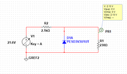
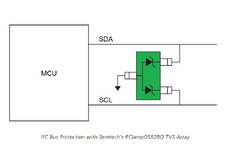
Hello, I want to protect I2C Pins of Raspberry Pico from ESD and for the purpose, as I learnt, TVS Diode will be used. So I'm using PESD5V0L1UA such as shown in schematic picture for a sensor with I2C and 5V operating. But I think this is not correct because of different output voltage.
Guide me to correct it and indicate something I'm missing to understand. As far I know, the diode should be short to ground when Reverse Breakdown Voltage meets to threshold (5V), thus stopping from overvoltage to I2C pins.
 

Attachments

  • I2C.PNG
    I2C.PNG
    9.9 KB · Views: 40
Hi,

with the 2100 Ohm and the 230 Ohm resistor in series you created a simple vopltage divider, resulting in the expected voltage of 2.13 V. Consequently, the TVS diode will not be conductive.

Further, the I²C pins are open-drain ones, meaining they are high-ohmic. So where is this 230 Ohm resistor coming from? I also miss the pull-up resistors required for an I²C bus.

What is your actual scenario? Why are you testing the circuit wit 21.6 V?

BR
I used 2.1k resistor to minimize current. Actually I'm not sure about the accurate circuit. 21.6V was just to use as surge voltage. Should I not use any resistor?
230 ohm was just as load.
The scenario is to protect I2C pins from surges coming from a sensor (Temp/Humidity or any other I2C sensor).
Please share accurate circuit for protection with this diode.
 
Hi,

In a technical view a rather vague description. In the order of appearance ;-) :
* ESD protection of PRi pico: The first step is to get the manufacturer´s specifications, because different chip ask for different protection solutions.
* You learned: please give a link to it, so we can discuss about the same informations
* TVS will be used: As already mentioned - it depends. I´m not a fan of TVS (as the only protection), because they (usually) don´t protect against positive ESD in case of RPi is powered OFF.
* PESD5V0L1UA: if we need to discuss about it´s function it´s always a good idea to post a link to it´s datasheet.
* Schematic: unclear: what is the ESD_injection node, the node_to_protect, where the values 2.1k Ohms, 230 Ohms, 21.6V come from
(I can guess that the ESD injection is at V1, but ESD voltage is expected to be in the kilovolts and the two resistors are totally unclear to me wether they are "real installed resistors, or port_internal ones, or the standard ESD_source_resistor...)
* short to ground: in the meaning of close_to_zero volt you are wrong. Current will flow, but the resulting voltage will be according datasheet chart .. always above the nominal diode voltage)

****
I recommend NOT to rely on random internet sources. They often contain errors and are incomplete.
I recommend to rely on semiconductor manufacturer´s informations. They are focussed, complete with detail informations, formulae .. and so on.

In most cases you will find dedicated (for I2C in your case) protection circuit recommendations, and even protection devices. No need to re-invent the wheel.

****
Basically: I2C means InterIntegratedCircuit .. usually kept on a PCB. In this case one does not need ESD protection at all. Thus I guess in your case the I2C leaves the PCB.
And thus the grade of expectable ESD voltage and energy depends on your usage. We don´t know what ESD voltages, capacitances, series resistance (and energy) we have to expect.

****
So it would help a lot if you could give context. As much as you know. We don´t know your level of electronics knowledge, and for sure we expect more details from an electronics expert than from a hobbyist.

Help us to help you.

Klaus
Klaus,
Thanks a lot for detailed response. I'm not a hobbyist but engineer with not much knowledge about ESD protection.
Mentioned TVS Datasheet link is given:

I just want to protect I2C Pins in case of ESD/surges from sensor side. ESD injection mode is sensor and protection will be on PCB (close to controller).
I could not find about recommended protection for I2C Pins of RP2040 based Pico.
I'm sure you would have done something similar, So you can suggest a circuit as the internet sources showing similar circuits as I found.

You can suggest a reference to study more about ESD protection.
 
Hi,

the PSED diode is actually an ESD diode, and not a dedicated TVS diode used to withstand EMC events. In case of EMC events, usually a series resistor is used as well, to limit the current, as there the energy is much higher.

In your initial schematic you used a PESD3V3U1UT which has a breakdown voltage of 5.8 V up to 6.9 V, now you are linking to one with 6.4 V up to 7.2 V. You have to decide which you you want to use, to make a proper design. With respect to limiting the current, here you have determine the actual voltage which might occure on your pin. E.g. for the PESD3V3U1U you would consider 6.9 V, where the logic level is 3.3 V. The GPIOs hav usually internal diodes connected towards VDD and GND. Assuming 0.3 V diode drop (w.c), the exceeding volatge at the pin is 6.9 V - 3.3 V - 0.3 V = 3.3V. Now you have to check whic overvoltaeg and consequently current into the GPIO can be dealed with. The GPIO can be protected by a series resistor, and a capacitor might be used as well, but therefore we need to know at which speed the I²C bus will be operated.

protection will be on PCB (close to controller).

Usually the diode is placed close to the connector, here the trace from the connector towards the pin represents an inductor and resistor. Further, a cross coupling into other lines is minimized.

BR
 
Hi,

the PSED diode is actually an ESD diode, and not a dedicated TVS diode used to withstand EMC events. In case of EMC events, usually a series resistor is used as well, to limit the current, as there the energy is much higher.

In your initial schematic you used a PESD3V3U1UT which has a breakdown voltage of 5.8 V up to 6.9 V, now you are linking to one with 6.4 V up to 7.2 V. You have to decide which you you want to use, to make a proper design. With respect to limiting the current, here you have determine the actual voltage which might occure on your pin. E.g. for the PESD3V3U1U you would consider 6.9 V, where the logic level is 3.3 V. The GPIOs hav usually internal diodes connected towards VDD and GND. Assuming 0.3 V diode drop (w.c), the exceeding volatge at the pin is 6.9 V - 3.3 V - 0.3 V = 3.3V. Now you have to check whic overvoltaeg and consequently current into the GPIO can be dealed with. The GPIO can be protected by a series resistor, and a capacitor might be used as well, but therefore we need to know at which speed the I²C bus will be operated.


Usually the diode is placed close to the connector, here the trace from the connector towards the pin represents an inductor and resistor. Further, a cross coupling into other lines is minimized.

BR
What would you suggest, how should I protect I2C Pins then? I'm confused about selecting components. What can be the correct circuit using PESD3V3U1UT?
 
Which senor are you using?
I²C clock frequency?
Cable length?
Which kind of cable?
Expected environment?
Expected ESD event?
One of the sensor is Humidity : https://eu.mouser.com/ProductDetail/Sensirion/SHT20?qs=gQ87q99/LGKEi6x5ZCXk4Q==
But it should be general protection i.e. for other I2C sensors as well.
--- Updated ---

Which senor are you using?
I²C clock frequency?
Cable length?
Which kind of cable?
Expected environment?
Expected ESD event?
Is this protection with TVS diode array, given in figure reliable?
 

Attachments

  • I2C_0582BQ.PNG
    I2C_0582BQ.PNG
    23.3 KB · Views: 26
Last edited:
Is this protection with TVS diode array, given in figure reliable?

The RClamp0582BQ has a maximum breakdown voltage of 11 V, so it is not reliable.

Please provide anserws to my previous questions, otherwise it is hard to support you.
 
Raspberry Pico and sensor are 3.3V IO, so you'll use 3.3V rather than 5V TVS, e.g. PESD3V3.

A 3.3V TVS has 3.3V stand-off voltage, leakage current at 3.3V < a few uA. Breakdown and clamping voltage (voltage @ 1 mA respectively some A) will be considerably higher. In so far a TVS diode will never fully protect a logic input and e.g. prevent forward biasing of processor and sensor internal ESD or substrate diodes, not even prevent device damage under all circumstances. It will however absorb a large share of ESD energy and increase the chance to survive serious ESD events.

For full protection of an exposed sensor line, you'd need stagerred overvoltage clamping and a protection impedance inbetween, e.g. a series resistor. That's not easily to achieve with I2C bus which is basically dedicated for low distance, intra-board communication.
 
Hi,

Again: most important is to know what are the limits of the PRi pins.
Then: What is your ESP pulse (worst case expected)
Then: your circuit, cable lengths, connectors, what node is "touchable", how and why...

****
Datasheet of post#5 says:
* breakdown voltage @5mA: max 7.2V. This yet is too high for a standard microcontroller input.
* clamping voltage @1A: 9V ... way too high...

****
Please give us informations we can work with.You are an enginerr, you know one needs values with units.

********
I used 2.1k resistor to minimize current.
This does not work with a standard ESD pulse.

21.6V was just to use as surge voltage.
ESD voltag is in the kV region. 21V is far from being considered ESD.

230 ohm was just as load.
On one hand you say I2C signals ... on the other hand you use a 230 Ohms load. What has the one to do with the other.

****
From your given informaions .. I guess you don´t know what ESD is. Please read about it, Please read about standard ESD test sources and test methods.


Klaus
 

LaTeX Commands Quick-Menu:

Part and Inventory Search

Welcome to EDABoard.com

Sponsor

Back
Top