Continue to Site

Welcome to EDAboard.com

Welcome to our site! EDAboard.com is an international Electronics Discussion Forum focused on EDA software, circuits, schematics, books, theory, papers, asic, pld, 8051, DSP, Network, RF, Analog Design, PCB, Service Manuals... and a whole lot more! To participate you need to register. Registration is free. Click here to register now.

EPROM flash and change

Deviousdexter

Junior Member level 1
Joined
May 1, 2024
Messages
16
Helped
0
Reputation
0
Reaction score
0
Trophy points
1
Location
UK
Activity points
177
Hello

I hope this the correct place to post this, feel free to move it if not.

Please excuse my ignorance but i require some knowledge please. I have an old 8 bit computer which i believe needs the BIOS Rom replacing, my intention is to replace it with an Eprom and flash it myself. I have purchased a cheap programmer form China and downloaded some software which i believe to be compatible. However, nothing i look at seems to list the chip i am trying to flash.

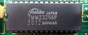
The original chip is a Toshiba TMM23256P which i would like to replace.

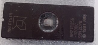
The replacement is an AM27C256-120DC which i think is an AMD IC (??)
( This is UV Erasable ? Is it usable or do i need something else?)

Pics attached.

The programmer is a SP200S-V2.00 which connects via USB using a CH340 Driver. And i have ASprogrammer. NEOprogrammer and WLPro-V220 that seem to lauch ok but not detect or list the specific chip(s) i have.
Do i need a different chip, a different program(s) or is this possible with what i have? All i have in way of a UV light is a curing light for solder mask, is this useable or not ?

Any advise is greatfully received.

thanks
 

Attachments

  • IMG_20240501_153822_3.jpg
    IMG_20240501_153822_3.jpg
    1 MB · Views: 159
  • IMG_20240501_154346_6.jpg
    IMG_20240501_154346_6.jpg
    784 KB · Views: 120
Not sure exactly what model of computer you have but most MSX machines use Z80 processors so their clock speed is no faster than 6MHz and more likely 4MHZ. They never made faster Z80s, the Intel range overtook them in the computer market although they were and still are used in some industrial systems. That means the chance of it running with a slower EPROM is good. Can program one for you here if you like, no charge, it is highly unlikely I will live long enough to use my IC stocks, I've got thousands of varied devices that are collecting dust (anti-static dust of course!).

Brian.
 
Ok ,the plot thickens. I checked the few machines i still have and none have a parallel port. Easy, i'll grab one of Amazon !. It arrives, get fitted and setup. The Eprom software is expecting a LPT on 0x378, according to Device Manager it is using EFF8-EFFF or EFF0-EFF& but software says its on 0xEC00(??)
1716059609289.png
1716062033553.png

i have added this to an IO.ini as per https://github.com/IceMupppet/willem-eeprom-programmer/blob/master/README.md
This does not seem to work, i am also still getting errors from the program on launch to do with extracting io.sys (??? ,i mention it now as i had assumed this may be linked to the lack of LPT on my machine, or the fact it is 64 bit)
The board LEDs have been lit at various stages, VPP is currently on, as the board is connected to LPT.

1716060612941.jpeg

Sorry about the size :(


The board also has a daughter board inthe connectors next to SP1, i have no idea what this does or if it should be there.
When launching the software, i get the following :-

1716060877466.png

1716060905279.png


The software then launches but cannot be closed without the "Privileged Instruction" warning and returning to the program ( i have to use task manager to quit the app).

I can select devices and change tabs without issue, but certain tasks cannot be executed showing the same behaviour as trying to quit.

I have tried a couple of compatibility modes to no avail.

Does anyone have any ideas ?

@betwixt - would like to explore a little further but would be very grateful if you have the time to do so, will gladly reimburse for any parts used.

thanks all
 
Last edited:
Now you know why I haven't touched Windows in years!

The port address problem is caused by Windows virtualization of the ports. In the old days a port, whether printer, serial or even USB was addressed by its real electrical port number, unfortunately for us, when multi tasking programs came along they created a big problem. Two or more programs running simultaneously would be able to write to the port at the same time, or at least share it with data from each program becoming interwoven. For example, one program could be trying to print a document while another tried to print graphics and what came out of the port would be an indescribable mess. Windows gets around it by creating virtual ports, to each program they appear to be a real port but they are in fact a software emulation of the real thing. Each program gets its own instance of the port. A different program called a "spooler" checks to see if anything is pending printing and ensures each port is serviced in sequence but only when its predecessor has finished its job. That way documents are printed one after another. Sadly, your programmer is trying to address the physical hardware port at 0x278 or 0x378, not the virtual one that Windows has created. I'm sure there is a way to solve the problem but I have little experience with later versions of Windows, I gave up on it when XP was around and switched to Linux instead.

If you send me your name and address through http://www.atv-projects.com/Contact.php I will program an IC and send it to you FOC.

Brian.
 
If you need a cheap UV source a UV power led might suffice....


Be aware do not expose your eyes or skin to any of these high power LEDs,
exercise caution.


If you need a cheap tool for spectral analysis : https://hackaday.com/2012/08/27/turning-a-webcam-into-a-spectrometer/
You would need a calibrated source to make measurements of absolute spectral power....


Regards, Dana.,
 
Last edited:
@betwixt - I have sent the info as requested. thanks again.

I hear what your saying about the address issue but some of the software in the GitHub is supposed to 'redirect' this address (from what i have read) and should allow this to function correctly. I never really put enough time or effort into Linux, which is a downfall on my part as i enjoyed playing around with RedHat many years ago when webpages were a buzz word. I have always tended to take what i need and research as far as needed to get it going. As always, i have my fingers in more pies than i have fingers. This project was meant to be a simple clean up and test of some old equipment,before selling it on to someone with more enthusiasm as i currently have, and hopefully get some enjoyment out of it. You are aware of the rabbit hole i went down from this thread.
Never the less, its all good for filling time and i undoubtedly will be in a similar predicament in due course :)

I will continue to 'play' and hopefully find a way to get things sorted or even find an older machine with a parallel port built in to repurpose. i've thrown so may away in the last 4 years to reclaim some space, it sooo annoying.

thanks go to anyone who has made a suggestion or linked info, it is really appreciated. Feel free to continue to offer advice as i will be looking into this as an ongoing project.

thanks
 
Got the email thanks.

Most UV LEDs radiate at about 395nM despite what the adverts say. Undoubtedly they will erase an EPROM but so will white light given long enough.
Ideally you want a UV source near 250nM, much shorter wavelength than a normal UV LED. They are available but at sky high prices.
Mercury vapor tubes are still the best solution and give best value for money. Typical UV LED directly touching the EPROM window will take up to 24 hours, a Hg tube will take about 10 minutes and could erase maybe 10 at a time if lined up.

Whatever is used, DO NOT STARE at the UV source, almost all the emitted light is invisible and is also far more damaging to your eyes than the visible part of the spectrum.

Brian.
 
I have managed to get some life out of this device and read the original IC from the 8 bit machine. Saving this out and comparing to the file i already have, shows them to be the same. RE-fitted the IC and reconnected to a TV but alas still no output than i can detect. The power LED is lit and the Caps LED toggles as it should, i will change the IC for anew one and try again.

In the meantime does anyone have a uk supplier of the LVA510 ic or a schematic so i can attempt to test it ? I have an oscilliscope to check pins if that is whats required ?

thanks

Edit: Out of curiousity does anyone know what the following board is for? it came attached to the programmer (it's a small daughter board) but has no components mounted. Fitted in the 24Cxx socket :-
20240522_1159_002_0.000.jpg
20240522_1159_003_0.000.jpg
 
Last edited:
Its an adapter so you can fit sockets for surface mounted ICs. Given the vintage of your MSX computer, it probably doesn't have any. Surface mounted ICs have either gull-wing legs (like normal pins but they sit flush to the board surface), J-legs which are like normal pins but curl under the edge of the IC or in some cases use BGA construction where there are no pins at all but pads under the IC body which directly solder to the PCB. You will note that in all cases the pins do not pass through holes in the PCB, hence the flat solder pads on the adapter.

I doubt you would be able to source LVA510 even when they were in production 30+ years ago. There are suppliers on eBay but they will be old stock.

Is it just the video that doesn't work? Does it beep or appear to be running the operating system but not display anything? I think the LVA510 is part of the video system and if faulty would probably leave everything else working normally.

Brian.
 
I have viewed a few video's which seem to point in the direction of the 2 IC's we have discussed. In one, the LVA510 is swapped out to correct a video issue, whether the same one i have or not is unknown.

This machine, as far as i remember, had a issue where the images would be fine but would only display in greyscale and was shelved and left. The 'no video' issue was a new issue from last time i started it, a few months back. I was looking to sell everything on as i mentioned earlier but i am reluctant to sell anything until i have tested it and, as i have a limited knowlegde but a vast internet of information at my disposal i thought i would attempt a repair first.

I suffered a Brain Hemorrhage and stopped work, so i have time to revisit some of the things i enjoyed but never persued as a career. As this machine is older tech, i thought it would be easier to see and work on :)

i have no knowledge of the LVA510 other than it is video related and i have seen it changed out in other instances of 'no video'.

Any info on said IC, that may aid in diagnosis of condition would be very helpful

The machine powers on ( LED lit) nothing on scrren but Caps Lock LED toggles when key pressed, cannot say i ever registered if there was any key sounds generated by system.

hope that helps.
 
I ordered a couple of LVA510 IC's which recently arrived. I put a socket on the board to allow swapping incase of faulty IC, which seems to be holding :)
Powered it up and behold a picture again and in colour ! Unfortunately the keyboard has a few non reactive keys so need a good clean but ithink we may have cured it.

@betwixt - i fitted the ROM and it is perfect - a very big thank you. I suspect the original may be fine as it matched the file contents of the ROM used.

Onto pastures new ...
 

LaTeX Commands Quick-Menu:

Similar threads

Part and Inventory Search

Welcome to EDABoard.com

Sponsor

Back
Top