Continue to Site

Welcome to EDAboard.com

Welcome to our site! EDAboard.com is an international Electronics Discussion Forum focused on EDA software, circuits, schematics, books, theory, papers, asic, pld, 8051, DSP, Network, RF, Analog Design, PCB, Service Manuals... and a whole lot more! To participate you need to register. Registration is free. Click here to register now.

[SOLVED] Echo canceller Schematic

Status
Not open for further replies.
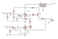
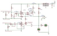
Here, sidetone elimination circuit is required not echo canceller. I came up with this, see in simulation.Upper trace is from Skype. Second trace is speaker input from GSM . Third trace is mixed audio on line. Fourth trace is extracted audio for GSM mic input. At a certain setting the audio on line is separated.


Adjust level of input/output to appropriate level being not too loud that it is distorted. Then adjust for deep null.
 
Last edited:
  • Like
Reactions: zentos

    zentos

    Points: 2
    Helpful Answer Positive Rating
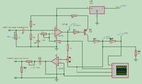
Here, sidetone elimination circuit is required not echo canceller. I came up with this, see in simulation. At a certain setting The audio on line is separated.
Upper trace is speaker input from GSM. Second trace is from Skype. Third trace is mixed audio on line. Fourth trace is extracted audio for GSM mic input.


Adjust level of input/output to appropriate level being not too loud that it is distorted. Then adjust for deep null.

I really appreciate the time afford for this matter and really thank you for this. Today I will make this and will test with my stuff and update you. BTW for the Q1 transistor any preferable value or any type of PNP will work for this. If you can mention any value, it would be great. Again thank you very much.
 

Any PNP transistor with power handling near 1W or more will do, such as BD136.
 

Any PNP transistor with power handling near 1W or more will do, such as BD136.
Capacitors are +ve towards LM358 and negative towards GSM connections for both input and output. There will be no current in transistor while line is not connected. Line will draw about 45mA. Check it with current meter. There will be around 7V on line. Check it with voltmeter. Don't forget to put filter capacitors on in ad out of regulator IC 7818.

I have build with exact values you have given. Both sides can hear, but audio quality not in good condition (lot of noise and broken). GSM side still has echo with connected power to circuit and without power (seems connection point makes some reflection or something.

As per your instruction I check the voltage values and seems some issue with the values. I check without plug telephone line and transistor points E=Vqe=17.6 V, B=V1=8.85V, C=Vqc=8.85V. Also IC pins without 4 and 8, other pins out 8.85v. I checked with transistor and without but no changes. Also checked with 2-3 LM356 (newly brought) but same.
R7 resistor considerably heating and I put 1W but still heating.
As per your video 5 pin out variable resistor does not change any voltage values in pin 1 output.


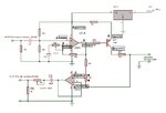
Here is Diagram with voltage values.
Edited Hybrid.jpg

I used this schematic for power supply. I'm not sure about is this need dual power supply (-18V to +18V).

18v-power-supply-LM7818-circuit.gif

Hope you will help me to fix this and I really thankful.
 

without power (seems connection point makes some reflection or something
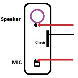
Yes, there should be no audio without power. This may be caused due to the fact that GSM speaker output is sometimes a differential output. The ground connection should be connected to chassis (Common negative ground plan) and only one wire to speaker terminal. Similarly only connect one wire to mic, ground connection will be the same. The audio should not leak through ground loops. Your power supply circuit is OK.
R7 and the other resistance on emitter of transistor are of equal value. They are in series. Both should heat up equally. You did not mentioned the current drawn by line. At 50mA, voltage drop on resistor be around 3V. Ohm's law tells the power dissipated in resistance= VxV/R= 9/100 = 0.1W.
Check voltage drop on these resistances. It seems the other 100 ohm resistance is shorted so that emitter is receiving full +ve voltage.

Make connections to GSM like this.
7876654300_1397811417.jpg


R1 can be eliminated.100k Variable with series capacitor in place of10k. It will not change basic performance of the circuit only due to availability of components. Her you can see expected voltages on different nodes. R7 here is not actual but represent load. LED will lit when line is off-hook.

Variable resistor will not change voltage on any pin but eliminate echo at certain setting.

R1 can be adjusted to set line voltage and current of line. You can hook ordinary phone with line output instead and observe audio quality and echo cancellation. Actually I am going to use this device as interface between PC and landline. If some relative is on SKYPE then I can transfer or make a conference call with another person who is not on SKYPE by dialling his number from landline phone and transfer line to SKYPE using this interface connected to headphone/mic of laptop.

Telephone sets have such type of circuit built-in. You can experiment connecting phone to line output of freetalk and connecting speaker output and mic input from its cradle to GSM without using any extra circuit.

Thanks for the update schematic. I played with new settings but couldn't able to eliminate echo. GSM side has mass echo even 100K whatever position(turning to low to high but not eliminate zero). For the 100K 0% point has small echo but both (skype and GSM sides) are not balanced. If GSM caller hears (with echo) low quality audio then Skype caller doesn't hear properly (can't understand whats talking).

I have checked the voltage value points. Those are same (0.5 V mines as my input 17.6V).
I checked line draw current and its 55mA. Last time (first schematic) it was 45 mA as you mentioned. Which means there was no errors and exact build.

I use common ground for GSM (used handsfree out with common ground). Also adjust load in to MIC and Speaker (with 10K potential meter) with 100K but no luck.

If you able to build this success please let me know. Thank you for looking in to this.
 

Try removing 33k in series with 100k to get further adjustment. 100k variable resistor may require carefull adjustment.
Do experiment with ordinary phone in place of freetalk and observe the audio on caller's side.
When echo is less, further adjust gain of input/output variables again. Repeat the process two three times to find optimum setting.

I did remove 33k and played with many settings. 0% of 100k point to telephone line side reduced some echo. With that mic and speaker adjustment able to eliminate ech0 100% but other side (skype) does not hear anything. If skype side hear (low quality) then GSM side appear mass echo with clear quality audio.

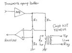
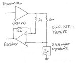
I found some hybrid Modules (From Chinese website). May be you can have a look.

tel_line_yeoeui_3.jpgtel_line_yeoeui_2.jpgtel_line_yeoeui_4.jpg

http://cast.bada24.net/spboard/board.cgi?id=study&action=simple_view&gul=14

Thanks.
 

These circuits demonstrate the basic principle that to feed equal amplitude but out of phase signal so that they cancel each other and the wanted signal remains.
Put a 100uF capacitor in parallel with 100 ohm resistor on emitter of transistor. Play with setting again.

First disconnect mic and adjust so that SKYPE listener hears GSM caller clearly. As mic is not connected there will be no echo and feedback. Now connect mic with low volume setting. GSM listener will hear SKYPE caller. Both will hear some echo. Reduce echo with variable. Increase mic volume and again adjust echo again.

I have tested as you mentioned. When mic (GSM) is not connected skype caller audio never comes clear. With the variable resister settings its increasing and decreasing. But its not going smooth flow. Some certain point its increasing around 30%. However I able to get some point which skype caller hear certain low quality audio. When connected mic then GSM side has mass echo. To avoid the echo I have to tune the skype caller (GSM Speaker) variable resister which I tune earlier.

If there is no echo on GSM side then GSM speaker side does not hear anything. I tried remove mic and connect speaker, then GSM side can hear quality audio without echo. But when I plug mic terminal echo comes.

Its very hard to balance audio and eliminate echo and its not possible with this settings as I'v tried lot.
 
Last edited:

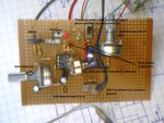
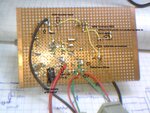
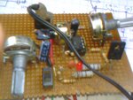
Can you post some pictures of your circuit assembly and connections setup?
 

Can you post some pictures of your circuit assembly and connections setup?

Here it is

Main1.jpgMain2.jpgMain3.jpg

- - - Updated - - -

Is it possible to add some transistors switches to receiver and transmitter with fine tune?

Usually in a telephone call both sides are not talking same time. When GSM mic input received audio signal then transmitter (Skype caller audio) should disconnect and the opposite. If those are switches well then it should like real conversation. But the main thing is it should be fine tuned and switch should be very fast. Otherwise it will be broken conversation.

Thanks.

Please note that with what ever settings of this schematic, receiver (GSM caller) audio not receiving properly (poor low quality audio).

Edited : Transistor switches for this has lot of negative impacts. If in a noisy background this will be more complicate.

- - - Updated - - -

I found some Electronic Hybrid 2 to 4 wire connection schematic. I have attached patent document with this. If someone can add the values or make this usable, really great for the community. I made lot of research (googled) but very hard to find working design.


https://patentimages.storage.googleapis.com/pdfs/US3855430.pdf
 
Last edited:

Is it possible to add some transistors switches to receiver and transmitter with fine tune?
Then you will be making a very simple and cheap speakerphone that has "voice switching". Motorola made two voice switching speakerphone ICs in the early '80ies.

Usually in a telephone call both sides are not talking same time.
Many phone calls have people talking at the same time but voice switching allows the other person (or noise) to hog or break up the voice direction.
Modern high quality speakerphones like from Polycom are "full duplex" so that both ends can talk at the same time and be heard with no acoustical feedback howling and no voice switching by using a modern echo canceller circuit. The echo canceller prevents sounds received from the other end and being picked up by the local mic from being transmitted back to the other end.

When GSM mic input received audio signal then transmitter (Skype caller audio) should disconnect and the opposite. If those are switches well then it should like real conversation.
People do not like voice switching because it cuts off parts of words. That is why modern full duplex speakerphones with echo canceller circuits are made and sold.
 

I find this confusing to understand.
When mic (GSM) is not connected skype caller audio never comes clear.
How will any audio pass through, from GSM, to GSM caller, when there is no audio on its mic input.
For example, you make a Skype call, put him on hold . Now you want to connect this call to another person on a distant location with a phone with him. You dial through your GSM to that phone and when call is established, you connect the Skype caller, who is on hold, through this device and the conversation begins.
Lets say there are three persons. One is on mobile phone end, second is you with GSM and freecall device and third is on Skype other side.
If there is no echo on GSM side then GSM speaker side does not hear anything. I tried remove mic and connect speaker, then GSM side can hear quality audio without echo. But when I plug mic terminal echo comes.

It should be like this, if mic is disconnected, the person on the phone ( GSM caller) will not hear sound from Skype freecall.
The person on Skype will hear the person on phone because there his speech is passing through speaker of GSM to the Skype. There is no feedback so the person on Skype(Skype caller) will hear the person on phone clearly.


Put a 470pF capacitor in parallel to 18K resistor between pin1 and 2 of the IC. I will assemble mine tomorrow and test it.


This is like one way communication at one time(half duplex). First make it working, then consider about echo problem which occurs only on duplex operation (when communicating both ways).
 

I find this confusing to understand.

How will any audio pass through, from GSM, to GSM caller, when there is no audio on its mic input.
For example, you make a Skype call, put him on hold . Now you want to connect this call to another person on a distant location with a phone with him. You dial through your GSM to that phone and when call is established, you connect the Skype caller, who is on hold, through this device and the conversation begins.
Lets say there are three persons. One is on mobile phone end, second is you with GSM and freecall device and third is on Skype other side.

It has to be corrected. During the GSM call remove mic terminals. So the GSM line active.


It should be like this, if mic is disconnected, the person on the phone ( GSM caller) will not hear sound from Skype freecall.
The person on Skype will hear the person on phone because there his speech is passing through speaker of GSM to the Skype. There is no feedback so the person on Skype(Skype caller) will hear the person on phone clearly.

What I mean is GSM side receiving quality audio with schematic but not for Skype caller audio. Seems it has to optimized.


Put a 470pF capacitor in parallel to 18K resistor between pin1 and 2 of the IC. I will assemble mine tomorrow and test it.

Will test and update you.

Update : I put 470uF and tested. Both sides can hear. skype side has small volume of audio. But still has echo on GSM side.
 
Last edited:

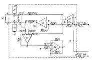
I found another full duplex audio circuit. Please have a look too.

**broken link removed**
full-duplex-audio-line.gif

This is similar circuit but has a fault. A3 polarity is shown reversed. This consist a Instrumentation_amplifier.
https://en.wikipedia.org/wiki/Instrumentation_amplifier

Second, it s good for connecting two speakerphones through a twin pair wire but the line drive is not compatible with telephone line. It support low voltage and low current only. Its impedance is high.

One important point is worth mentioning. FreeTalk device has two outputs. On one point an ordinary phone is connected. On second point, telephone line is connected. This device we made is to be connected with the point where landline is connected, not with telephone output connecter. Both points can communicate speech.
For telephone line we needed to provide DC voltage and current similar to telephone line so we made 18V supply.
I overlooked the point that on phone line output, this voltage is already available from the device. We can make use of it and make device compatible with phone line output. This would make a simple circuit powered from Freetalk device itself.
Attach a phone hear and observe voltage on line when phone is off-hook and the current drawn by it.
 

One important point is worth mentioning. FreeTalk device has two outputs. On one point an ordinary phone is connected. On second point, telephone line is connected. This device we made is to be connected with the point where landline is connected, not with telephone output connecter.

I'm bit confused. Freetalk has 1 output (Regular Phone) and 1 input (Telephone line). So connecting this schematic to telephone line does not make any sense. Because I'm saying when skype call received only regular phone rings and I checked other line (telephone line) whether giving any signal. Its voltage 0 without connected telephone line. I dont have telephone line.

So make this work for regular phone output similar to using a telephone connection. Only different is freetalk connect to skype instead of PSTN line.

I checked voltage output on regular phone output and its 47.1 V. Line draw current when off-hook is 0 mA and hook position its 18.3 mA.
 

Oh! that's why it is not working. Let me redraw it for work as regular phone.
 

Status
Not open for further replies.

Similar threads

Part and Inventory Search

Welcome to EDABoard.com

Sponsor

Back
Top