Venkadesh_M
Advanced Member level 4

- Joined
- Jun 26, 2013
- Messages
- 1,374
- Helped
- 258
- Reputation
- 516
- Reaction score
- 254
- Trophy points
- 1,363
- Location
- Coimbatore, India
- Activity points
- 8,020
Follow along with the video below to see how to install our site as a web app on your home screen.
Note: This feature may not be available in some browsers.


BradtheRod this not seem to work in all frequencies...... Isnt it??


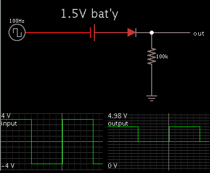
Try this


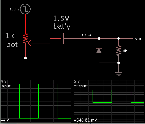
Ya the modified circuit could do the job perfectly if the 100k replaced by a 10k............ I just draw a modal which is easy to understand...Also notice the battery receives a charging current of a few mA when the input is -4V. Some types of batteries cannot tolerate this.
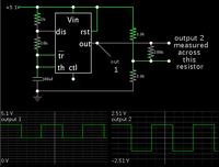
I already said that. this circuit cant be used for higher loads.. and for the ground concern it can be used for different ground configurations....f the load draws too much current, the output level will drop. This will require raising the supply V at the 555 IC

Elex-factor:
Thanks for your help. I tried the above circuit and the voltage level shifted. However, the voltage range was much higher than 5 V even when the input was between -3 and 3 V. How could i shift down the output voltage? I am using 500 ohm potentiometer instead of 200 ohm. Also, what value should i keep the potentiometer to? Does the output voltage depends on potentiometer resistance? Please help.


Depends on what you want to do with your output.You could use a simple resistive divider to bring 0-10 V to 0-5 V.
But what is it that you want to do with that 0-5 V output ?????
