Continue to Site

Welcome to EDAboard.com

Welcome to our site! EDAboard.com is an international Electronics Discussion Forum focused on EDA software, circuits, schematics, books, theory, papers, asic, pld, 8051, DSP, Network, RF, Analog Design, PCB, Service Manuals... and a whole lot more! To participate you need to register. Registration is free. Click here to register now.

DS1307 RTC Accuracy Rate

Saeedk9574

Member level 3
Member level 3
Joined
Nov 6, 2023
Messages
66
Helped
0
Reputation
0
Reaction score
0
Trophy points
6
Visit site
Activity points
516
Hello everyone,
Do you Know, how much the tolerance of ds1307 RTC is per day?
Most importantly, is this time tolerance a fix value or it has random error. Can we fix this problem with code?
 
DS1307 has internal caps too. Sounds like you need smaller cap values. The 10 ppm difference between both devices seems to indicate initial crystal tolerances.
Hi,

... and a breadboard is not suitable for such a circuit. It´s stray capacitance and stray inductance is too high.
And different (brand) breadboards may give different results.

Indeed I don´t expect higher frequency when adding capacitors. This tells me there is a different problem. (PCB layout, power supply noise, coupled noise, temperature ...)

--> For reliable (test) results you need to keep on the design recommendations of both the DS1307 manufacturer as well as the XTAL manufacturer.

Klaus
I knew that the breadboard test was not reliable I just wanted to do this test before testing it on PCB, However, I did not to expect to see such drift with caps. This time I will test it with 12pf caps on PCB and I will share the results here.
 
Last edited:
After using different values of load caps (15pf and 12 pf) for crystal, it was not precise at all. It was just sometimes faster and sometimes slower. it even has drift in one day. So I realized caps are not the issue.
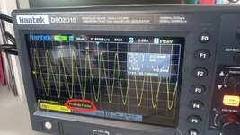
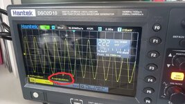
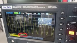
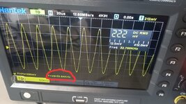
I checked my crystal waveform on oscilloscope and its frequency. that was fluctuating between 32.89 and 32.64kKHz.
Do you know this frequency is OK for the clock crystal or not?
 

Attachments

  • photo11656793490.jpg
    photo11656793490.jpg
    79.6 KB · Views: 80
  • photo11656793385.jpg
    photo11656793385.jpg
    81.9 KB · Views: 78
  • photo11656793333.jpg
    photo11656793333.jpg
    88.3 KB · Views: 72
  • photo11656793262.jpg
    photo11656793262.jpg
    77.9 KB · Views: 76
You do realize that the scope probes themselves probably add more load capacitance than the physical capacitors and the scope measures frequency by timing between peaks of the waveform so will have a degree of inaccuracy and instability. You should check the frequency using the SQW output where the probe is isolated from the crystal by the DS1307's internal divider and also you have sharp edges on the waveform to trigger the scope with.

Follow the manufacturers guidelines, keep crystal wiring as short as possible and avoid passing other signals nearby. There is a layout diagram in the data sheet, consider that you probably already add too much wiring length and certainly too much capacitance in the breadboard connections themselves.

Brian.
 
Your scope probes at 10X have a specified Cload.

You can decouple that with a series R from probe tip to xtal test point. Then the
effective Cprobeloading =

1716803268499.png

Of course your amplitude response is affected, but if all you care about is freq measurement....

The above transform equivalency often used in impedance matching circuit design, RF.

Or use a FET probe.....

Also low cost scopes are not exactly high precision frequency measurement devices in terms of drift,
accuracy, repeatability......

Also use scope on infinite persistence, AC coupled, say 100 mV / box, and look at power supply rail noise.
Might be an eye opener.

Google "rtc xtal pcb layout", that can be quite instructive.

Capacitor ESR considerations (power supply bypassing effectiveness) :

1716803989178.png


Regards, Dana.
 
Last edited:
.. or in other words

you try to measure ppm accuracy with a non suitable setup. Thus - as you can see - the results vary a lot. The results are not reliable at all.
They don´t give any useful information.
And do simple math on your own: your measured frequencies how a variation of about 7600ppm .. which equals to

As mentioned several times ... accuracy depends a lot on temperature and noise, stray capacitance, stray inductance .... rectify this before you can do useful tests.

Klaus
 
You do realize that the scope probes themselves probably add more load capacitance than the physical capacitors and the scope measures frequency by timing between peaks of the waveform so will have a degree of inaccuracy and instability. You should check the frequency using the SQW output where the probe is isolated from the crystal by the DS1307's internal divider and also you have sharp edges on the waveform to trigger the scope with.

Follow the manufacturers guidelines, keep crystal wiring as short as possible and avoid passing other signals nearby. There is a layout diagram in the data sheet, consider that you probably already add too much wiring length and certainly too much capacitance in the breadboard connections themselves.

Brian.
As breadboard was not realizable I put it aside. Now I am testing on PCB. The crystal is totally near to the IC and tracks are as short as possible. I had supposed SQW pin is making an square wave. With this pin how can I
Your scope probes at 10X have a specified Cload.

You can decouple that with a series R from probe tip to xtal test point. Then the
effective Cprobeloading =

View attachment 191086
Of course your amplitude response is affected, but if all you care about is freq measurement....

The above transform equivalency often used in impedance matching circuit design, RF.

Or use a FET probe.....

Also low cost scopes are not exactly high precision frequency measurement devices in terms of drift,
accuracy, repeatability......

Also use scope on infinite persistence, AC coupled, say 100 mV / box, and look at power supply rail noise.
Might be an eye opener.

Google "rtc xtal pcb layout", that can be quite instructive.

Capacitor ESR considerations (power supply bypassing effectiveness) :

View attachment 191087


Regards, Dana.
Thanks for sharing these information. I should take them into consideration and I did some of them. I guess probably I have bought low quality or the fake one the ic and crystal.
--- Updated ---

.. or in other words

you try to measure ppm accuracy with a non suitable setup. Thus - as you can see - the results vary a lot. The results are not reliable at all.
They don´t give any useful information.
And do simple math on your own: your measured frequencies how a variation of about 7600ppm .. which equals to

As mentioned several times ... accuracy depends a lot on temperature and noise, stray capacitance, stray inductance .... rectify this before you can do useful tests.

Klaus
I try to take the many of these issues into the account. Even though I had not used load cap, short tracks, I would not have had 20 seconds drift per weeks. With this explanation cant we say IC or the crystal are faulty themselves? isn't it possible the components are fake?
 
Last edited:
The DS1307 is basically an oscillator and a chain of digital dividers to convert the 32768Hz oscillations into seconds, minutes, hours and date. It is highly unlikely the digital dividers give wrong results but it is possible the oscillator part is not to original manufacturers specification and somehow pulls the crystal off frequency. However, Quartz crystals are mechanical devices and their accuracy is decided by how well they are made, it is more likely to be a problem with the crystal than the IC.

I make an assumption that the supply voltage is stable and you have a decoupling capacitor directly across the IC supply pins.

For interest, many years ago I was involved in calibrating wristwatches. They also used a 32768Hz crystal but being very small it wasn't possible to apply probes to measure the frequency. Instead I used a special microphone and frequency selective amplifier to listen to the quartz vibrations. The sound was then compared to a precision reference and a tiny variable capacitor in the wristwatch was adjusted to zero beat the two oscillations. Even then, refitting the back on the watch body would shift the timing.

Brian.
 

LaTeX Commands Quick-Menu:

Similar threads

Part and Inventory Search

Welcome to EDABoard.com

Sponsor

Back
Top