Continue to Site

Driving PFET with PIC

Status
Not open for further replies.
The base resistor connected to the PIC I/O is usually 10K as per looking around the net and seeing various projects out there. Could I drop this a 4.99K for a quicker turn on time? Do I need to?
Adding a small capacitor (like 10-100pF) in parallel with the base resistor should provide faster switching, without requiring the PIC to drive significantly more current.
 

So I provide schematics, and everyone runs away! :-o

I'm thinking this through, but I really don't see an issue with changing the PFETS at the LED cathodes for logic level NFETs that are driven by the same I/O's as the indicator LED's. This allows me to remove 10 - 15 components from the design and greatly saves space.

Please, any thoughts on this?
 

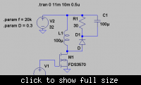
If your load is just LEDs, which do not need to be referenced to any specific voltage, then yes you can use different switching topologies with N channel fets. Here's a circuit I've used to drive LEDs in the past:

This is a buckboost converter, where the load is referenced to the input supply voltage, instead of ground. If you need feedback and regulation, then you'll probably need some kind of differential feedback amplifier, though.
 

Ahh, the buck converter is working just fine. What i'm trying to do is switch in or out the LED from the buck converter. In the schematic I have a PFET doing this but I have to invert the signal from the PIC I/O. I was wondering if connecting a logic level NFET would work the same? This would mean I can remove the transistor and pull up resistors from the circuit, which act as the inverters so that the PFET is off when the PIC I/O is low.
 

Ahh, the buck converter is working just fine. What i'm trying to do is switch in or out the LED from the buck converter. In the schematic I have a PFET doing this but I have to invert the signal from the PIC I/O. I was wondering if connecting a logic level NFET would work the same? This would mean I can remove the transistor and pull up resistors from the circuit, which act as the inverters so that the PFET is off when the PIC I/O is low.
You mean this schematic?

What I see there are some incorrect FET symbols (they have the body diode direction of a N fet but the channel indicator for a P fet. The symbols in buck converter schematic are also wrong). Looking at how they're used in the schematic, it looks like they should be N fets. So I'm not sure what you're referring to here...
 

Yes, I've discovered earlier today that those symbols are wrong in the component library. They were PFETS in the actual design. I have since fixed this issue completely and replaced the PFETS with logic level NFETS.

The buck converter works on the bench so I will have to assume, I havent checked it yet, that the schematic symbol is also wrong here. It should be a high side PFET with a 3904 working as an inverter on the PIC I/O line thus that when the I/O line is high, the PFET is conducting.
 

Status
Not open for further replies.

Similar threads

Part and Inventory Search

Welcome to EDABoard.com

Sponsor

Back
Top