Continue to Site

Driving PFET with PIC

Status
Not open for further replies.

JMG

Member level 3
Member level 3
Joined
Sep 27, 2005
Messages
66
Helped
0
Reputation
0
Reaction score
0
Trophy points
1,286
Activity points
1,908
Greetings everyone,

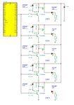
I am having an issue with a very basic circuit. I am trying to drive a PFET at 15kHz via PWM output from a PIC. I have the PWM going into the base of a 3904 transistor, the collector is connected to the PFET gate and a 22K resistor is connected to the supply (27 - 32V.) The emitter is connected to ground.
The PFET will turn on and off very slowly thus it is getting very hot as its operating in linear mode. My gate signal on the scope looks like an arc rather than a nice square wave. At 1% duty cycle I have the equivalent of about 35% duty cycle worth of ON time.

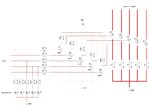
I will post up a schematic and some pics of the scope shortly to help visualize what I am saying.

The whole circuit is actually a buck converter to drive 24.6V @ 2.1A of LED's. It simulates nicely, but this is reality! :lol:
 

A hand calculation gives 10 us rise time order of magnitude, so you obviously would want to use a somewhat more sophisticated gate driver. Two more transistors or an integrated gate driver can easily achieve it.
 

FvM, could you provide the equation you used to evaluate rise time? Thanks.
mister _rf, I will give that a go and update the thread with results. Dont like the idea of dropping 30mA through a resistor though.

---------- Post added at 19:33 ---------- Previous post was at 18:51 ----------

Hmm well, 1K killed the output of the PIC after ~30 seconds. Oops. I didn't get time to take a look at the waveform but I did get dimming as the PWM duty cycle changed.
 

I didn't calculate a rise time because I don't know the actual FET data, just estimated an order of magnitude. Rise time will be about double time constant Cg*R. Cg is effective gate capacitance, considering the miller effect, may be 1.5 - 4 times Cgs.

Dont like the idea of dropping 30mA through a resistor though.
That's why I suggested additional transistors. Most simple solution is a complementary voltage follower behind the 22k load resistor.
 

tr9a.gif

I have considered you are using this diagram. Changing value for ‘R6’ from 22k to 1k doesn’t force supplementary current on the PIC output…
 

Changing value for ‘R6’ from 22k to 1k doesn’t force supplementary current on the PIC output.
Yes, I assumed, that JMG rather complains about resistor power dissipation.

One point should be corrected. 24V is exceeding the permissible gate-source voltage of most MOSFETs. You should add a second resistor to form a voltage divider, applying e,g, 12 to 15 V Vgs.
 

The initial idea to lower ''up to'' 1k, so there are many value in between the two: 10k, 4.7k, 2.2k :-D
 
Last edited:

A hand calculation gives 10 us rise time order of magnitude, so you obviously would want to use a somewhat more sophisticated gate driver. Two more transistors or an integrated gate driver can easily achieve it.
hello fvm,
how you calculated 10 us rise time.would you please quote the formula?
 

I didn't "calculate 10 us rise time". Please refer to post #5 for details. For an exact calculation, you have to consider miller capacitance and output voltage as well.
 

tr9a.gif

I have considered you are using this diagram. Changing value for ‘R6’ from 22k to 1k doesn’t force supplementary current on the PIC output…

Yes that is exactly what I am using. Instead of the light bulb, the load is an inductor used in a buck converter.

Yes, I assumed, that JMG rather complains about resistor power dissipation.

One point should be corrected. 24V is exceeding the permissible gate-source voltage of most MOSFETs. You should add a second resistor to form a voltage divider, applying e,g, 12 to 15 V Vgs.

I had not considered the gs voltage. My mistake.

The initial idea to lower ''up to'' 1k, so there are many value in between the two: 10k, 4.7k, 2.2k :-D

I actually used a 2.49K :)

I was thinking of a circuit like this


Unfortunately too many components. There are 2x 5 FETs to drive. So 5 buck converters, 12 LED's, 6 switches, several connectors, a PIC and a 5V 1A power supply all in 100mm diameter pcb, components on one side only.
 

Unfortunately too many components.
You can either have simple one transistor driver stage or low power driver. Or use dedicated gate driver ICs.

P.S.: You can have a NPN/PNP transistor combination in a single 3x2.5 mm SOT23-6 package, or in an even smaller SOT-363 one.
 
Last edited:

That is very true. **broken link removed**

I looked at gate drivers and think I am confused. They all seem to be used in driving N channel fets. Can/how are they used to drive a P channel?
 

A high side gate driver could be used with a static supply instead of the usual bootstrap circuit. Unfortunately, the polarity is reversed, resulting in default on state of the driver. Or use standard "low side" drivers with a level shifted power supply. But there's probably no perfect solution for PFETs.
 

Ok, so I have this working fine now using a lower value resistor and a 3904 transistor. I get exactly what I need. I am not sure why the original PIC died.

Couple more questions.

The base resistor connected to the PIC I/O is usually 10K as per looking around the net and seeing various projects out there. Could I drop this a 4.99K for a quicker turn on time? Do I need to?

The PWM signal needs to be split and sent to the collectors of 5x 3904's. Each 3904 can be switched on and off independently to drive each buck converter as needed. Does anyone see a problem with this? There is a single 10k resistor between the I/O pin and the 5x bases.

The cathode of the LED's is connected to a 0.1r resistor and then on to a PFET to ground, to connect or disconnect the LED's as required. The signal for this PFET is also shared with an indicator LED. I am thinking of changing the PFET with a logic level NFET so that the NFET turns on when the indicator LED is turned on. Theoretically I should be able to drive the indicator LED at 10mA and the NFET gate from a PIC I/O line. Agree or disagree?

Thanks.
 

Try to make a schematics, that more easy to analyze and improve for the best solution. :cool:
 

This is the behavior of a pic16 pins as you sink/source more current

PIC16F_VOL-IOL.gif....PIC16F_VOH-IOH.gif

and these are the absolute max ratings

Clamp current, IK (VPIN < 0 or VPIN > VDD)........ 20 mA
Maximum output current sunk by any I/O pin........25 mA
Maximum output current sourced by any I/O pin........25 mA

I don't think that the mcu can be damaged with a 1k resistor at the output and as you wrote it was actually 2.49K so the current was even lower.

Alex
 

See some diagrams for example: :cool:


It's not so clear how to control each bipolar transistor. Using a switch for each transistor?
 

Attachments

  • PIC test 1.JPG
    PIC test 1.JPG
    138 KB · Views: 133
  • PIC test 1 ON_OFF control.JPG
    PIC test 1 ON_OFF control.JPG
    142.1 KB · Views: 142

Ok, I provided a few schematics.

First the outputs and switching of the power LED's. The user can select how many LED's are turned on and there is an indicator LED for each power LED turned on. I have used the output from the PIC for each indicator LED to turn on the base of a 3904 which turns on a PFET, which connects the cathode of the power LED's to the current sense resistor, which is connected to ground.

My original question was, can I change these PFETs to logic level NFETs and remove the 3904 transistors and still be able to provide 10mA to the indicators LED's and turn on the NFET?

Second questions was regarding the PWM signal. I've changed this slightly. The PWM signal is sent to the base of five 3904 transistors, each turning on a PFET in the buck converter. Is it acceptable to drive 5 3904's from a single PIC I/O? Will there be noise issues here?
 

Attachments

  • PWM.jpg
    PWM.jpg
    107.2 KB · Views: 143
  • indicatorLED_PFET.jpg
    indicatorLED_PFET.jpg
    100.5 KB · Views: 156

Status
Not open for further replies.

Similar threads

Part and Inventory Search

Welcome to EDABoard.com

Sponsor

Back
Top