Continue to Site

Welcome to EDAboard.com

Welcome to our site! EDAboard.com is an international Electronics Discussion Forum focused on EDA software, circuits, schematics, books, theory, papers, asic, pld, 8051, DSP, Network, RF, Analog Design, PCB, Service Manuals... and a whole lot more! To participate you need to register. Registration is free. Click here to register now.

double volt-ampermeter with pic

Status
Not open for further replies.
Check you`re mail!
I want to replace the letters like : U, I, P and R from Display with values units SI like ,V-from volts, A-from ampers, W-from watts, Omega-for ohms.
 

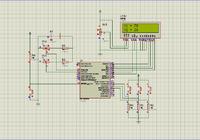
Check this. The floating point to string conversion is not working properly. If the i/p value is changed it gives wrong values. Do you know C?
 

Attachments

  • ss12.jpg
    ss12.jpg
    179.2 KB · Views: 136

click the play button and stop buttons to simulate. The buttons are at the bottom left. There is still some problem with A and R values float to string conversion.
 

Attachments

  • adc.rar
    17.8 KB · Views: 155
Last edited:
  • Like
Reactions: Vlad.

    Vlad.

    Points: 2
    Helpful Answer Positive Rating
yes. hmm. it`s a hard one. but is much easy to make 2 voltmeters and 2 ampermeters? or this is better with power and rezistance? Because I can accept will dual VA. no problem. All i want a VA digital
 

Any thing can be done. Only if floating point value is converted to string properly. Wait I have asked the mikroe people about the float to str problem. Hope they give some solution.
 

Just a small problem with the power measurement. check the attached file.
 

Attachments

  • ss13.jpg
    ss13.jpg
    189.7 KB · Views: 149
  • vlad2.rar
    17.8 KB · Views: 161

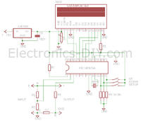
Sorry , is goot , mess up the hex`s, and the schematic will be this from the last no? and where is the calibration buttons? and this schematic don`t need quatrz crystal?
 

I didn't code for the calibration button, so I removed it. Modify the schematic I sent and add buttons and mention what the buttons should do clearly. How the calibration is done. etc.,
 
  • Like
Reactions: Vlad.

    Vlad.

    Points: 2
    Helpful Answer Positive Rating
Problem is that: i have made pcb and i put all componets exacly like this schematic
will be majore modification on the that schematic now? with the last code(the good one)? i observe a reset push buton, and i don`t see the quartz crystal for external osccilator
 

pIn proteus it doesnlt matter if you add crystal or not. It simulates either way. but in real hardware you will need the crystal. If you dont want the reset button you can remove if. Draw your version of circuit in proteus and zip and upload the .dsn file. And tell exactly how calibration is done.
 

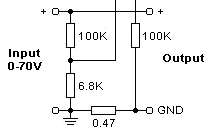
The schematic is like yours, I modify only the shunt rezistor(RV3) to 0.47Ohms. i will let the reset button. Tell me the circuir work good without calibration button? because if will work good i remove them.
 

The circuit I sent is calibrated for 70 V and 10 A. If you want 500V and some other amp range to be included. The code has to be written for that. What higher value do you want to measure. I can provide I button such that on pressing the button, the measurement mode changes to 500 V range. Will that be ok?
 
  • Like
Reactions: Vlad.

    Vlad.

    Points: 2
    Helpful Answer Positive Rating
yes. you can put to measure a range 500V and 30 or 50 amps? on this case i need to calculate the rezistor to divider?
Can you change please the start up mesage to`Welcome Vlad`?
 

I will make it 500 V and 50 A. You send me the .dsn file. I will code. I need the interface circuit.
 
Last edited:

I think so. You have to calculate the resistors. I think you need to have two set of input circuits. Can you explain how both sides of 0.47 Ohm resistor is connected to GND? With that cicuit A reads 0.00 Amps. I think you have to use 714k and 6.8k. Check it.
 
Last edited:

Status
Not open for further replies.

Similar threads

Part and Inventory Search

Welcome to EDABoard.com

Sponsor

Back
Top