Continue to Site

Welcome to EDAboard.com

Welcome to our site! EDAboard.com is an international Electronics Discussion Forum focused on EDA software, circuits, schematics, books, theory, papers, asic, pld, 8051, DSP, Network, RF, Analog Design, PCB, Service Manuals... and a whole lot more! To participate you need to register. Registration is free. Click here to register now.

Does the code indicated in the picture below actually produce the waveform attached?

Newbie level 1
Joined
Jun 5, 2024
Messages
1
Helped
0
Reputation
0
Reaction score
0
Trophy points
1
Activity points
9
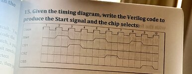
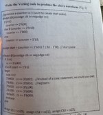
I can’t seem to agree that the code does produce the waveform pattern in the image? From the code it seems like the register “cs” is loaded only every time start=1 (which is once in 3 clock cycles according to its assign statement code)

So cs1 would be 1 for 3 clock cycles i.e. cycles 3,4,5
cs2 would be 1 for 3 clock cycles i.e. cycles 6,7,8
cs3 would be 1 for 3 clock cycles i.e. cycles 9,10,11

Does anyone else agree or disagree?

Thank You
 

Attachments

  • IMG_0684.jpg
    IMG_0684.jpg
    508.9 KB · Views: 56
  • IMG_0682.jpg
    IMG_0682.jpg
    1.5 MB · Views: 58
Hi,

1500 kBytes of picture .... for about 0.5 kBytes of text. This is a factor of 3000.
Would you mind to reduce file sizes?

Klaus
 

LaTeX Commands Quick-Menu:

Similar threads

Part and Inventory Search

Welcome to EDABoard.com

Sponsor

Back
Top