Continue to Site

Welcome to EDAboard.com

Welcome to our site! EDAboard.com is an international Electronics Discussion Forum focused on EDA software, circuits, schematics, books, theory, papers, asic, pld, 8051, DSP, Network, RF, Analog Design, PCB, Service Manuals... and a whole lot more! To participate you need to register. Registration is free. Click here to register now.

DIY Moving Message Display

Status
Not open for further replies.
Send me the code and schematic.I do not understand why are u using 595 for rows.Any way it seems that it is the problem of scanning rows delay.Remember the proteus has frame and time step adjustment in its animation enviroment.Increase the delay between rows.When u simulate in proteus it might be display that all rows are ON but when in hardware it solves ur problem.If the problem remains,send me the code.
 

Hey to everyone....i want built a "Wireless Announcement Board". I would like to use a PC to send the data out(using RS232 port) to Microcrontroller,the data(a word or character) will display on dot-matrix screen. I found many similiar project in this forum and most of the project using cable to connect RS232 port and microntroller. For me, i want to make it wireless(no cable is used to connect RS232 port and microntroller).
Anyone can help me? Pls.......
Anyone of u have a good idea for this "Wireless Announcement Board" beside the meathod i meantion.
 

Hi Guys, i have successfully build a simple text scroller. it`s scroll text from right to left. i want to scroll from bottom up or up to bottom but i have no idea about the code..anyone can help me with the sample code? in picbasic? sorry for my bad english because i`m an Indonesian. thanks very much..
 

dear erio
unless you show your hardware its difficult to suggest you, share your hardware and then its easy to give you an idea.
 

sn_burki said:
dear erio
unless you show your hardware its difficult to suggest you, share your hardware and then its easy to give you an idea.

ok then...sorry i forget to post the schem and code..here it is...the code in picbasic pro and the schematic.

PS: it looks weird on proteus, but believe me, in the real world, it looks nice with a little flickering..

now, after the first message is scrolled, i want to add second message who scrolled from bottom up or up to bottom..veery lot of thanks for helping me..


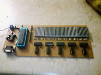
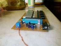
I have made 2 of these kind of circuits, this verison can take on string from Computer using serial port using 8051.Previous one, I did was around a year ago. It also used 8051. I also have pictures of previous board and video demonstration.
 

umery2k75 said:


I have made 2 of these kind of circuits, this verison can take on string from Computer using serial port using 8051.Previous one, I did was around a year ago. It also used 8051. I also have pictures of previous board and video demonstration.

nice and neat thing..can u post schem and the code? so i can learn it..
is this can be operated standalone? i mean the message is stored on EEPROM? or just receiving the message from the serial?

thanks before...


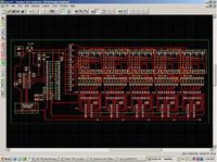
I don't have schematic, I had written lots of code for these kind of hardware. This program doesn't make use of Serial, it's easier to understand.In this PCB design I forget to add the base resistor of transistor, which I added in the end.If you want this file of EasyPC then tell me, I will upload it.

#include<reg51.h>

sbit P2_0=P2^0;
sbit P2_1=P2^1;
sbit P2_2=P2^2;
sbit P2_3=P2^3;
sbit P2_4=P2^4;
sbit P2_5=P2^5;
sbit P2_6=P2^6;
sbit P2_7=P2^7;

sbit P3_6=P3^6; // Data
sbit P3_7=P3^7; // Clock

code character[]={0xff,0xff,0xff,0xff,0xff,0xff,0xff,0xff,0xff,0xff,0xff,0xff,0xff,0xff,0xff,0xff,0xff,0xff,0xff,0xff,0xff,0xff,0xff,0xff,0xff,0xff,0xff,0xff,0xff,0xff,0xff,0xff,0xff,0xff,0xff,0xff,0xff,0xff,0xff,0xff,0xff,0xff,0xff,0xff,0xff,0xff,0xff,0xff,0xff,0xff,0xff,0xff,0xff,0xff,0xff,0xff,0xff,0xff,0xff,0xff,0xff,0xff,0xff,0xc1,0xdd,0xdd,0xdd,0xe3,0xff,0xc1,0xd5,0xd5,0xdd,0xff,0xc1,0xf5,0xf5,0xfb,0xff,0xc3,0xf5,0xf5,0xc3,0xff,0xc1,0xf5,0xf5,0xeb,0xdf,0xff,0xfd,0xfd,0xc1,0xfd,0xfd,0xff,0xc1,0xfb,0xf7,0xfb,0xc1,0xff,0xc1,0xd5,0xd5,0xdd,0xff,0xc1,0xfb,0xf7,0xef,0xdf,0xc1,0xff,0xfd,0xfd,0xc1,0xfd,0xfd,0xff,0xff,0xff,0xff,0xe3,0xdd,0xdd,0xdd,0xe3,0xff,0xc1,0xf5,0xf5,0xfd,0xff,0xff,0xff,0xff,0xc3,0xf5,0xf5,0xc3,0xff,0xc1,0xf5,0xf5,0xfb,0xff,0xc1,0xf5,0xf5,0xfb,0xff,0xc1,0xdf,0xdf,0xdf,0xff,0xc1,0xff,0xc1,0xd5,0xd5,
0xdd,0xff,0xc1,0xdd,0xdd,0xe3,0xff,0xff,0xff,0xff,0xc1,0xf5,0xf5,0xfb,0xff,0xc1,0xf7,0xf7,0xc1,0xff,0xfd,0xfb,0xc7,0xfb,0xfd,0xff,0xdb,0xd5,0xd5,0xed,0xff,0xc1,0xff,0xe3,0xdd,0xdd,0xdd,0xff,0xdb,0xd5,0xd5,0xed,0xff,0xff,0xff,0xff,0xff,0xff,0xff,0xff,0xff,0xff,0xff,0xff,0xff,0xff,0xff,0xff,0xff,0xff,0xff,0xff,0xff,0xff,0xff,0xff,0xff,0xff,0xff,0xff,0xff,0xff,0xff,0xff,0xff,0xff,0xff,0xff,0xff,0xff,0xff,0xff,0xff,0xff,0xff,0xff,0xff,0xff,0xff,0xff,0xff,0xff,0xff,0xff,0xff,0xff,0xff,0xff,0xff,0xff,0xff,0xff,0xff,0xff,0xff,0xff,0xff,0xff,0xff,0xff,0xff};


void Flush(void)
{
unsigned int a;

P3_6=0; // Data=0, Filling with 0s
P3_7=0; // Clock=0, Ready

for(a=0;a<63;a++)
{
P3_7=1; // Low to High Transistion
P3_7=0; // High to Low Transistion
}

}

void main(void)
{
unsigned int i,j,k,offset;

Flush();
while(1)
{
P3_6=1;

P2=character[0];
for(j=1;j<=100;j++) ;


P3_7=1;
P3_7=0;

P3_6=0;

for(i=0;i<63;i++)
{

P2=character[i+offset];
for(j=1;j<=100;j++) ;


P3_7=1; // L to H
P3_7=0; // H to L
k++;
}
if(k==128) { offset++; k=0; }
if(offset==206) { offset=0; k=0; }


}
}

Added after 4 minutes:

This is one MSOFFICE files that I made during designing, there is another one also.
 

umery2k75 said:


I don't have schematic, I had written lots of code for these kind of hardware. This program doesn't make use of Serial, it's easier to understand.In this PCB design I forget to add the base resistor of transistor, which I added in the end.If you want this file of EasyPC then tell me, I will upload it.

#include<reg51.h>

sbit P2_0=P2^0;
sbit P2_1=P2^1;
sbit P2_2=P2^2;
sbit P2_3=P2^3;
sbit P2_4=P2^4;
sbit P2_5=P2^5;
sbit P2_6=P2^6;
sbit P2_7=P2^7;

sbit P3_6=P3^6; // Data
sbit P3_7=P3^7; // Clock

code character[]={0xff,0xff,0xff,0xff,0xff,0xff,0xff,0xff,0xff,0xff,0xff,0xff,0xff,0xff,0xff,0xff,0xff,0xff,0xff,0xff,0xff,0xff,0xff,0xff,0xff,0xff,0xff,0xff,0xff,0xff,0xff,0xff,0xff,0xff,0xff,0xff,0xff,0xff,0xff,0xff,0xff,0xff,0xff,0xff,0xff,0xff,0xff,0xff,0xff,0xff,0xff,0xff,0xff,0xff,0xff,0xff,0xff,0xff,0xff,0xff,0xff,0xff,0xff,0xc1,0xdd,0xdd,0xdd,0xe3,0xff,0xc1,0xd5,0xd5,0xdd,0xff,0xc1,0xf5,0xf5,0xfb,0xff,0xc3,0xf5,0xf5,0xc3,0xff,0xc1,0xf5,0xf5,0xeb,0xdf,0xff,0xfd,0xfd,0xc1,0xfd,0xfd,0xff,0xc1,0xfb,0xf7,0xfb,0xc1,0xff,0xc1,0xd5,0xd5,0xdd,0xff,0xc1,0xfb,0xf7,0xef,0xdf,0xc1,0xff,0xfd,0xfd,0xc1,0xfd,0xfd,0xff,0xff,0xff,0xff,0xe3,0xdd,0xdd,0xdd,0xe3,0xff,0xc1,0xf5,0xf5,0xfd,0xff,0xff,0xff,0xff,0xc3,0xf5,0xf5,0xc3,0xff,0xc1,0xf5,0xf5,0xfb,0xff,0xc1,0xf5,0xf5,0xfb,0xff,0xc1,0xdf,0xdf,0xdf,0xff,0xc1,0xff,0xc1,0xd5,0xd5,
0xdd,0xff,0xc1,0xdd,0xdd,0xe3,0xff,0xff,0xff,0xff,0xc1,0xf5,0xf5,0xfb,0xff,0xc1,0xf7,0xf7,0xc1,0xff,0xfd,0xfb,0xc7,0xfb,0xfd,0xff,0xdb,0xd5,0xd5,0xed,0xff,0xc1,0xff,0xe3,0xdd,0xdd,0xdd,0xff,0xdb,0xd5,0xd5,0xed,0xff,0xff,0xff,0xff,0xff,0xff,0xff,0xff,0xff,0xff,0xff,0xff,0xff,0xff,0xff,0xff,0xff,0xff,0xff,0xff,0xff,0xff,0xff,0xff,0xff,0xff,0xff,0xff,0xff,0xff,0xff,0xff,0xff,0xff,0xff,0xff,0xff,0xff,0xff,0xff,0xff,0xff,0xff,0xff,0xff,0xff,0xff,0xff,0xff,0xff,0xff,0xff,0xff,0xff,0xff,0xff,0xff,0xff,0xff,0xff,0xff,0xff,0xff,0xff,0xff,0xff,0xff,0xff,0xff};


void Flush(void)
{
unsigned int a;

P3_6=0; // Data=0, Filling with 0s
P3_7=0; // Clock=0, Ready

for(a=0;a<63;a++)
{
P3_7=1; // Low to High Transistion
P3_7=0; // High to Low Transistion
}

}

void main(void)
{
unsigned int i,j,k,offset;

Flush();
while(1)
{
P3_6=1;

P2=character[0];
for(j=1;j<=100;j++) ;


P3_7=1;
P3_7=0;

P3_6=0;

for(i=0;i<63;i++)
{

P2=character[i+offset];
for(j=1;j<=100;j++) ;


P3_7=1; // L to H
P3_7=0; // H to L
k++;
}
if(k==128) { offset++; k=0; }
if(offset==206) { offset=0; k=0; }


}
}

Added after 4 minutes:

This is one MSOFFICE files that I made during designing, there is another one also.

thanks umery2k75 for sharing with me..unfortunately i`m not familiar with c language..but many2 thanks..
i`m still waiting for help from the others to give a hint how to scroll message from bottom tu up or up to bottom

thanks and best regards
 

hi to all..anybody is doing interfacing 8x8 dot matrix display with 89c51 controller give me circuit diagram..and code.
 

umery2k75 said:


I have made 2 of these kind of circuits, this verison can take on string from Computer using serial port using 8051.Previous one, I did was around a year ago. It also used 8051. I also have pictures of previous board and video demonstration.

Your one is the best among all, neat easy and simple, but if you could give the Schematic, code in assembly and all details.
 

**broken link removed**

Any suggestions on taking this project and doubling the rows from 8 to 16?
 

they all use mikrocontroller to control data. my circuits not use micro, i just use that IC shift register, n pararel port to send data. anyone can help me, or give me some clue to program that circuit. thx
 

#include <AT89X51.H>

unsigned int del,i,x,j,y;


unsigned char a[5]={0X24,0X22,0X22,0X22,0X24};

void main (void)
{
P1=0X00;
P2=0X00;
while(1)
{

for(x=0;x<5;x++){ //for felay to show the moving effect
for (j=0;j<10;j++){ //for felay to show the moving effect

y++;

P2_0=1; //LAT
P2_1=1; //CLK
P2_1=0;

for (i=0; i<5 ;i++) {
if( (i+y) > 5) {
P1=0x00;
for (del=0;del<25;del++);
P1=0X00
for(del=0;del<12;del++);
}
else{
P1=a[i+y];
for (del=0;del<25;del++);
P1=0X00;
for(del=0;del<12;del++);
}

P2_0=0;
P2_1=1;
P2_1=0;
}
}}
}//end of while
}
 

Status
Not open for further replies.

Part and Inventory Search

Welcome to EDABoard.com

Sponsor

Back
Top