Continue to Site

Welcome to EDAboard.com

Welcome to our site! EDAboard.com is an international Electronics Discussion Forum focused on EDA software, circuits, schematics, books, theory, papers, asic, pld, 8051, DSP, Network, RF, Analog Design, PCB, Service Manuals... and a whole lot more! To participate you need to register. Registration is free. Click here to register now.

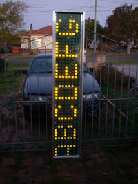
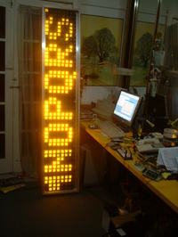
DIY Moving Message Display

Status
Not open for further replies.
I av used 89v51rd2 microcontroller, a decoder to select one row at a time, 8 shift register to which data is serially bitwise sent. The shift reg controls the scrolling display for 8 (5*7)led matrix [7 rows,5 cols, anode=row,cathode=col]. Now I am breaking my head on developing the code to control scrolling display. Can nebody explain me wrt to 1 character suppose 'A' wat codes to send to decoder and shift reg to display it scrolling.
 

for color generation (true colors) on LED you have to use FPGA.
 

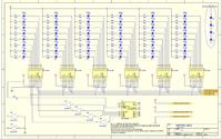
Altered schematic for sign with PIC16f648a:
up to 248 character long :?:


:lol:
 

Attachments

  • 648MOVING SIGN.rar
    7.8 KB · Views: 371
  • 648MOVING SIGN.pdf
    25.9 KB · Views: 384
Ha, another one who dislikes matrix :)
But, it is much cheaper to use HC595/ULN2803 combo instead of MIC.

Anyhow, good job.

Hello Zoran,

That is true, only why I use them because I get few tubes sitting on shelf and I pay for ea. around $0.20 AUS. So why not to use them? Still was cheaper for me than to buy a HC595 + 2803. Less parts to put on the board for me as well.:lol:

Ebay prices now:
MIC5841 around $7.00 AUS ea.
74HC595/ 54HC595 around $2.50 - $4.70 AUS. for 10 pcs.
ULN2803 around $5.50 AUS. for 10 pcs.

However, no one stoping anyone to modify the circuit, parts and the design is only suggestion for the people which like to learn.

Anyhow, good suggestion for another people.
Hugo:lol:
 
Well, HC595+ULN2803 combo works pretty well, even is dimmable/PWM :lol: (Hint: OE pin of 595)

The only downside is that for each 64 LEDs there are 8 HC's and 8 ULN's needed

Made a couple displays, 8, 16 and 24 bits height (single color, of course). Most expensive parts are PCB's :shock:
 
Re: cd4514 led scroll circuits

sir could you please give me the code.

---------- Post added at 15:07 ---------- Previous post was at 14:53 ----------

can you help me in providing the code for scrolling display
 

Well, HC595+ULN2803 combo works pretty well, even is dimmable/PWM :lol: (Hint: OE pin of 595)

The only downside is that for each 64 LEDs there are 8 HC's and 8 ULN's needed

Made a couple displays, 8, 16 and 24 bits height (single color, of course). Most expensive parts are PCB's :shock:

You right with the PCB, but if you not need the flashy PCB (which is in the box anyway) you can do only small board with IC’s and large Perspex board with the LED’s
The original design was without the dimming, but I must added dimming because is located on road and at night time was to bright:razz:
 
Re: cd4514 led scroll circuits

Sorry i don’t do that anymore after experience on this board, begging (saying it is for my church..) for source and.... than you find out on this board claiming as OWN. https://www.edaboard.com/threads/52169/


sir could you please give me the code.

---------- Post added at 15:07 ---------- Previous post was at 14:53 ----------

can you help me in providing the code for scrolling display

Regards
 

Re: cd4514 led scroll circuits

sir could you please give me the code.

---------- Post added at 15:07 ---------- Previous post was at 14:53 ----------

can you help me in providing the code for scrolling display

Code comes with the PREPAID bill :) together with correct circuit diagram and proposed PCB layout.
The only "catch" is that the ammount has 4 zeroes :)

MOD: Nice reply..i like it. It may be noted by the members who expect full projects for free..:)
 
Re: cd4514 led scroll circuits

MOD: Nice reply..i like it. It may be noted by the members who expect full projects for free..:)

Yup, there's no such thing as a free lunch :lol:

It's, sometimes, easy to help someone boosting his/hers mind in thinkering when they hit the brick wall, but everything???

Time = Money

And some of us spent a lot of time educating ourselves and trying to stay in the main flow (as much as it is possible).
 

My 16ch (16 x 5x7 leds) MMD project, now full with source!

Hi my friends;
I made this circuit in 2007 and uploaded it here in 2008:
https://www.edaboard.com/threads/11364/#post574682
It was my first major PIC project in Proteus.
More than 80 (!) people asked me (and received) the Proton Basic source, but ... no feedback :-( .

OK, now here is the entire project, the source too. Since then I completed a few things,
this is the latest version (attached). For recompiling use Proton 3408 (max. 3506).

I do not deal with it already (no support !!! :)), but maybe someone can use it ...

zuisti
 

Attachments

  • zuisti-16char-full.zip
    81.8 KB · Views: 529
I get PS as below but very limited info in.

hope you can assist, i bought some display module 16x32 matrix they are intented for training in the school were a teach. bought iam yet to get the module work. the interface for connectio have 16 pins the module back i could raed 74HCT595, 74HCT138, 74HCT02. do you have idea?


HI,
I have an idea of your board the 595 is the shift register(shift 8 ), 138 is the 3 of 8 decoder and 02 is the NOR gate, which mean the display can be 8x8 dots (I assuming) but if you have more IC’s on than you can multiply the columns and even rows. But to help I need more info about your board not only the IC‘s which is on. 16 pin connector doesn’t mean anything until you supply “pins connection”. The info about your display board is NOT ENOUGH to help you.
Regards,
 

Hi. I'm working on some scrolling text circuit, with 2 different messages. I'll put it on the locked door. When the door is locked, it says "put your card on the sensor" and when the door is opened, it says "door is open", etc. I want to use 16f877 and 8x40 leds. I checked some projects but i really don't know where should i begin. I don't understand how to make pc connection, actually i don't really need that. The messages can be stored in the programming step and we don't need to change them frequently.
 

I get PS as below but very limited info in.


HI,
I have an idea of your board the 595 is the shift register(shift 8 ), 138 is the 3 of 8 decoder and 02 is the NOR gate, which mean the display can be 8x8 dots (I assuming) but if you have more IC’s on than you can multiply the columns and even rows. But to help I need more info about your board not only the IC‘s which is on. 16 pin connector doesn’t mean anything until you supply “pins connection”. The info about your display board is NOT ENOUGH to help you.
Regards,

Thanks alot.
i can give you detail about the display in attachment. however the board is product of EVTECH i could read 2CH00929A at the back of the display,
the features are: 74HCT595 are arranged 4x4 column and rows, all pin 13 are grounded, all pin 12 are connected together, all pin 11 are connected together, all pin 10 are connected to 5V, from the first register, pins 9 is connected to 14 of the next register, it pin 9 is connected to pin 14 of the next, the loop contihue to the last.
on each output of the register four cathode of the LEDS are connected.
 

Hi. I'm trying to build this circuit. It works with 4 displays, but if i want to increase the number of displays, i can't synchronize them, 4 of them scrolls ok, but the 5th one doesn't keep up with them. How can i do that?

asd.jpg
 

Edit: Solved.
 
Last edited:

It is nice to say SOLVED but how the will be nice to explain and every one can learn.
Hugo
 

Status
Not open for further replies.

Part and Inventory Search

Welcome to EDABoard.com

Sponsor

Back
Top