Continue to Site

Welcome to EDAboard.com

Welcome to our site! EDAboard.com is an international Electronics Discussion Forum focused on EDA software, circuits, schematics, books, theory, papers, asic, pld, 8051, DSP, Network, RF, Analog Design, PCB, Service Manuals... and a whole lot more! To participate you need to register. Registration is free. Click here to register now.

Designing with INA3221

engr_joni_ee

Advanced Member level 3
Joined
Nov 3, 2018
Messages
807
Helped
2
Reputation
4
Reaction score
7
Trophy points
18
Activity points
6,728
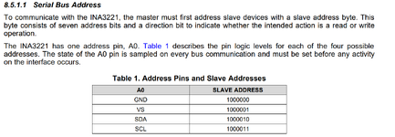
I am working with adding INA3221 in my schematic. I am wondering about the address pin. There is only one address pin Ao. The pin Ao can be attached to GND, VS, SDA, or SCL. Does it means only four devices INA3221 can be attached to I2C bus ?

The slave addresses (7 bits) mentioned in Table 1 in the datasheet has only four different addresses which corresponds to four Ao connection options.

Question: How can we add six INA3221 to I2C ?
 

Attachments

  • Untitled 754.png
    Untitled 754.png
    70.7 KB · Views: 33
Like always ...

You ask a question about a specific device, but don´t give a link to it´s datasheet.
If you don´t want to invest the time.. I don´t either.

From the shown table it seems there can "only" be 4 such devices on the bus. But why "only"? Many I2C devices don´t offer 4 different addresses.

Without having a look into the datasheet: you always have the option to use different I2C busses, or split an I2C bus using an "I2C MUX"

Klaus
 
Thanks I will either use I2C Multiplexer or add another I2C bus in the design.

Regarding the value of shunt resistor. I did following calculation.

According to datasheet, the maximum voltage across shunt resistor is +/- 163 mV.

I have 3.6 A max running through the power cables. The supply voltage at the load is 3.3 V.

I found 39 mOhm through hole resistor having power rating 3 W tolerance +/- 5%. I also found SMD with tolerance 1%.

The voltage across shunt resistor will be

V = I x R

V = 3.6 x 39/1000

V = 140 mV

The power dissipation across shunt resistor will be

P = V x I

P = 140/1000 * 3.6

P = 0.5 Watt

What will be the resolution of the current measurement ?

Considering 2 bit noise in 13 bit ADC.

3.6 A / 2048 = 1.75 mA

Is my calculation make sense for 11 bit ADC ?

Link to datasheet INA3221 is

 
Last edited:
Hi,

I´m positively surprised. You did some math.

* 39mOhms is correct
* 140mV is correct

Resolution is independent of noise. ADC is 13 bit.
According datasheet the "shunt step size" is 40uV. According Ohm´s law: I = V / R = 40uV / 39mOhm = 1.03 mA step size = resolution.

Errors are:
* ADC_offset (and drift)
* ADC_gain (and drift)
* ADC_noise
* ADC_nonlinearity (INL)
* wiring
* shunt resistor tolerance
* shunt resistor drift
* maybe more

Klaus

PS:
your link is rather long, with a lot of unnecessary informations.
it could be:
* https://www.ti.com/lit/ds/symlink/ina3221.pdf
* or INA3221 datasheet (using the [Insert Link] button)
.. but well done to link directly to the manufacturer´s homepage.

Klaus
 
Last edited:
One last point in this thread is the calculation of junction temperature for INA3221. The datasheet is already shared above.

There are three contributors when it comes to power.

1- Quiescent supply power
2- Input bias power
3- Shunt measurement power

First is the Quiescent supply power. According to datasheet, the Quiescent current is between 350 uA to 450 uA. Let's take the mid value which is
equal to 400 uA.

Supply Quiescent power: IQ x Vs = 400 uA x 5 V = 2 mW

Second is the input bias current.
Input bias current at IN+ = 10 uA
Input bias current at IN- = 10 || 670 μA || kΩ

I am taking 10 uA as input bias current.

The value of shunt resistor is 0.39 mOhm and the shunt resistor voltage is 140 mV. Can I take 70 mV as common mode voltage ? Please comment of the value of common mode voltage (VCM)

Input pin power (for 2 pins): 2 x IN+ x VCM = 2 x 10 uA x 70 mV = 1.4 uW

Thirds is the shunt measurement power.

Vbus measurement power: (VCM/Vbus_Impedance)*VCM = 0.5 W

The total power will be the sum of all three contributions which is almost equal to 0.5 W.

Junction-to-ambient thermal resistance according to section 7.4 of datasheet is 36.5 degC/W

The junction temperature will be equal to ambient temperature (consider 40 degC) + 0.5 W x 36.5 degC/W = 58.25 degC.
 

LaTeX Commands Quick-Menu:

Similar threads

Part and Inventory Search

Welcome to EDABoard.com

Sponsor

Back
Top