Continue to Site

Welcome to EDAboard.com

Welcome to our site! EDAboard.com is an international Electronics Discussion Forum focused on EDA software, circuits, schematics, books, theory, papers, asic, pld, 8051, DSP, Network, RF, Analog Design, PCB, Service Manuals... and a whole lot more! To participate you need to register. Registration is free. Click here to register now.

Controlling AC load using IGBT

Status
Not open for further replies.

Mithun_K_Das

Advanced Member level 3
Joined
Apr 24, 2010
Messages
899
Helped
24
Reputation
48
Reaction score
26
Trophy points
1,318
Location
Dhaka, Bangladesh, Bangladesh
Activity points
8,254
Controlling AC load using IGBT is not new idea. But as far I tested, IGBT get too hot with a little amount of AC load. Is this really possible to run heavy load such as 1~3KW using IGBT?

What I'm talking about is this:
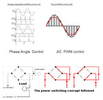
Soft_Start_Of_Induction_Motor_by_AC-PWM_Abstracts.jpg

Please share your opinion about this technology.

Note: I've tested with 100W of AC load so far. But I saw many industrial systems those are working this way so smoothly. Although all of them had enough cooling fan or even few was water cooled.

What I got, if I run a AC Lamp, it doesn't become so hot, but if I load a Fan of the same power, IGBT gets hot.
 

PWM static voltage regulator

This is the latest technology of voltage regulation to provide real-time control of voltage fluctuation, sag, surge and also to control other power quality issues such as spikes and EMI/RFI electrical noises. This uses an IGBT regulator engine generating pulse width modulated (PWM) AC voltage at high switching frequency. This AC PWM wave is superimposed on the main incoming wave through a buck-boost transformer, to provide precisely regulated AC voltage. The regulation in this technology is instantaneous, thus making it suitable for electronic machines which need precise regulated power.
_wikipadia.
 

The problem with the circuit in post #1 is that it's no buck regulator with storage inductor and free-wheeling/commutation current path but a only a simple switch.

The circuit has a least this problems
- it can't be legally operated without massive filters due to huge amount of high-frequent noise generated by the pwm switch.
- by the working of circuit inductances, the transistor voltage will rise to high values during switch-off, most likely exceeding the IGBT's Vcemax and probably destroying the transistor.
 

One thing you need to seriously think about will be non resistive power factor loads.
What happens when you open the circuit, how can the current keep flowing ?
It will not of course, but the result will be some massive voltage spikes across your IGBT with lagging power factor.

I have only ever seen IGBT control of ac with resistive loads, typically heating elements and dimming of high wattage stage lighting.
They do not high frequency chop the ac, but use conventional phase control.

The main advantage of this is you can use the leading half of each half cycle, or the lagging half, or the bit in the middle symmetrical around the peak.
 

So what will be best for mixed load at home or office use. Lights, TV, PCs, FAN etc are the common loads. Should I think about Thyristor technology?
 

Static Voltage regulator using IGBT. What is your opinion about this type of regulator?
They are using PWM sine inverter to generate a corrective voltage that is added to/substracted from the input voltage and can work with all kind of loads.

The circuit hasn't much to do with your simple chopper circuit in post #1.
 

Another issue related to the topology on the post #1 is the fact that it significantly increases the cost of the equipment, particularly for higher loads, where the price of the power devices represents the major part of the overall cost.
 

So will it(static voltage regulator) be reliable for mixed load if the system is used at home/office, FvM?
Sure, but possibly too expensive.
 

Expense will be an important issue. But in Tap changing type voltage regulator, voltage is being regulated with a difference of 20~30V. I mean, it works like this: once it goes to 220+20 = 240V, then changes to 220-20=200. Then again increases up to next tap is switched on/off. So it is like one kind of voltage fluctuation.

But in static voltage regulator, output is almost same and static all the time. This is why, it will be a good regulator I think. But cost will be an important issue for power devices.
 

Its becoming much more difficult to design anything that actively switches or chops the mains directly, that will pass EMC requirements these days and its getting tougher all the time.

To have reasonable reliability it must also survive massive fault currents and abuse sufficient to trip an up stream thermal circuit breaker.

The average member of the public can be pretty stupid and have totally unreasonable expectations about what they can plug into the mains supply, or into your power conditioner.
And if it does blow up, its all your fault if its still under warranty.
 

For an inductive load like a motor, a path has to be provided for the freewheel current of the motor windings, when the choper MOSFET / IGBT switches OFF. This is done by the additional bridge rectifier and switch. The 2nd switch is driven by the complement of the main PWM drive. The transient suppression diodes protect the power switches (see attached fig.)
 

Image file was not displayed.
Uploaded "AC_chopper.jpg" again
 

Attachments

  • AC_chopper.jpg
    AC_chopper.jpg
    13.4 KB · Views: 376

The circuit can work - theoretically.

In practice, the high frequent current feed to the mains and high frequent voltage across the load will make it hard up to impossible to comply with EMC regulations.

Existing static voltage stabilizers or controllers are keeping all high frequent signals inside a shielded box with respective filters towards the outside.
 

I tested one of the converter like this. Whenever I turn it on, my PC monitor shuts down. Also, cell phone network fluctuates. I checked the wave shape, its the worst. So I think it is not a good idea for inductive loads.
 

The pwm ac-chopper concept shown in the figure is just a bare outline. To realize a practical working converter, many design features have to be implemented, some of which are:

1. Use of fast power rectifiers in the bridge rectifier.
2. Incorporation of dead band in the complementary IGBT drive waveforms.
3. Incorporation of a soft start algorithm in the MCU firmware to limit inrush currents.
4. Incorporation of EMI filter in the mains, using amorphous toroid inductor and a capacitor.
5. Minimising Switch-off losses in the IGBT's.
and so on...

The fast bridge rectifies and associated IGBT are now being replacd by two series connected IGBT's, in practical industrial applications.

There is an interesting (though now outdated), reference design available here:

**broken link removed**
 

hello,why can`t you think about the use of TRIAC for AC motor control?I hope it should be the easiest method.Why are you preferring to use IGBT ?
 

So what will be best for mixed load at home or office use. Lights, TV, PCs, FAN etc are the common loads. Should I think about Thyristor technology?
The old fashioned way is either a motor driven variac in buck/boost configuration, an SCR zero crossing switched tap changer on a suitable transformer, or a ferroresonant constant voltage transformer.
An extreme case might be a rotary converter of some kind to change the frequency as well.
On the plus side, these primitive methods are extremely simple, robust, idiot proof and have proven high reliability.

All these systems can cope with horrendous short term fault currents, extreme power factors, and introduce very few new nasties onto the power distribution system.

To do it all better with some modern light weight high frequency silicon, may be asking rather a lot, especially with current and prospective conducted EMC regulations.
 

Irrespective of the bad EMC predicates of the circuit shown on post #14, it sounds like redundant. There is no reason to split each half cycle of the wave among two PWM switches. Once the input voltage is pre-rectified, just one bridge/Mosfet suffice.
 

Status
Not open for further replies.

Similar threads

Part and Inventory Search

Welcome to EDABoard.com

Sponsor

Back
Top