Continue to Site

Welcome to EDAboard.com

Welcome to our site! EDAboard.com is an international Electronics Discussion Forum focused on EDA software, circuits, schematics, books, theory, papers, asic, pld, 8051, DSP, Network, RF, Analog Design, PCB, Service Manuals... and a whole lot more! To participate you need to register. Registration is free. Click here to register now.

Conductive Anodic filament - ESD diode intermittent failure

shaan122

Newbie
Joined
Jan 16, 2011
Messages
3
Helped
0
Reputation
0
Reaction score
0
Trophy points
1,281
Activity points
1,320
Would conductive anodic filament (CAF) formation occur internal to the Diode? Are there any technical papers related to that? I am facing a component failure unrelated to ESD and after exposed to high temp (45C) and low humidity (6% RH) conditions, the issue is getting resolved. The diode is 41206ESD and it is used in the power on circuit. This is preventing device to not power on/restart, etc. Intermittent behavior. Any suggestions would be appreciated.

Thanks.
 
You can see conductive filaments or "junction spikes" in
some metallurgical systems (we used to see "emitter pipes"
in bipolar processes, where abuse could make aluminum
follow slip defects all the way through the base). This can
be provoked by overstress and proceed over time if the
silicon material has the wrong kind of defects and no
barrier metal or TiN is used to stabilize the contact
metallurgy.

Making lemons out of lemonade, you can also make a "zap
zener" do the same entraining of aluminum into silicon by
high localized power whether there's a pre-existing defect
or not.

However this kind of thing is -not- reversible by a low temp
dry bake. Perhaps you have more of a simple moisture
problem and maybe some ionic contamination driving the
resistance down, in the device encapsulation (or on the board,
not the diode body itself). Driving off the water would make
the residue less or non conductive, "resetting" the problem,

If you remove a "bad" diode does it still leak?

If you bake a removed "bad" leaky diode does it clear up?
 
Yes, I removed all the traces to the diode on the PCB and baked it and it fixes the issue. Even if I blow the hot air/apply a soldering iron to the diode it fixes the issue. In the diode construction, there is a layer of this diode, which is epoxy and maybe it is prone to moisture absorption.
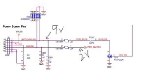
However, what is tricking me is that in the attached circuit, only diode channel 3 has this low resistance issue, and never saw it on any other channel. How the moisture is impacting only one channel even the channel 4 has a higher bias voltage.
To see moisture impact, I tried to re-create the failure by placing the PCBA in a 50C 95%RH environment for 10 days with no success.

2024_02_29_20_59_45_WfxNWWindow.jpg
 
Perhaps the epoxy is poorly cured and the bake makes it "freeze"
anything mobile when it finally does cure?

Might try, if this is consistently happening, pre-baking the diode
(quad) before assembly to test that one out. If it's true, field returns.
Including the ones already ruined.

Perhaps voltage or the leakage power initially, also accelerates some
sort of "curing". I don't usually deal with plastic packaging (you may
come around to the same view) and sounds like this packaging may
be inferior to standard mold compound (which can be had in super
low moisture absorbtion grade).

Have you searched for reliability related info on this part type and
manufacturer? Looking at the datasheet, is the package drawing one
that you can maybe also research, find source vendor and qualification,
reliability and angry-customer data?

Now you don't say quantitatively, just what "low resistance" means.
The POR reference makes me think maybe this clamp sits on the RC
timer node and at some point its leakage exceeds the pullup current
and the reset never releases.

If this is true then you may also have a design marginality or other
components to blame. For example if the C is leaky, same outcome?
Or the two gang up on the R and defeat the release because the
threshold is too high and somebody picked 10Mohms for R so
they could use a cheaper smaller cap (caps vary by V and C while
resistors pretty much not, so cheap it is). But then leakage matters,
where if you went down a decade on R and up a decade on C, no
prob.

Perhaps you have test access and info you are not using. Do you
measure POR release threshold (independent of UVLO)? Know
where threshold is and measure open circuit node voltage, are
you comfortably on the right side of it or one foot in the manure?

Good parts should not bake in or bake out. That's a fact. But you
might be more of a hero if you identified the contributing factors
and a resilient fix(es) as well. Like, if the ones passing are the ones
whose caps don't leak, anything in the field that develops a leak
might come back under warranty and then whoever sold it will be
looking for someone to pass the buck (or something that rhymes)
to.

One of my uncles had an Apple II that failed that way. Poking the
RSTb pin showed it stuck low-ish. New cap, all better.

Is the "failing" diode the one at the end or in the middle? Maybe
middle ones get residue that doesn't fully clean until cooked.

Is a 100% 50C unpowered bake too costly to get the job out the
door, while you investigate at more leisure? Still recommend the
full failure analysis, because gut says it's a "sum-of" kind of problem.
 
The diodes are rated for "• Chemical resistance: ASTM D-543, 24 hrs @ 50°C, 3 solutions (H2O, detergent solution, defluxer)"

I don't know if aqua deflux is used or what the exposure time to high humidity in the reported failures were, but I have a hunch the problem may be with the solder profile🔥🔥🔥.

Hypothesis: If the epoxy seal degrades after thermal shock in the liquidus pulse, then moisture ingress will be a problem.

How many ppm or % fail or qty. fail with this mode?

1709274469247.png
 
Last edited:
@dick_freebird I missed mentioning the diode resistance value when it is in a failure state. It mostly ranges from 2 K to 7K, But it is consistent if no external forces (temperature) are applied.
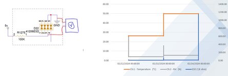
I experimented with a problem PCBA. I removed the cap and ferrite using a wire stripper, isolated the diode and bias from an external supply, and left it in an environmental chamber. See the attached result.
ESD_test.JPG
This same diode is used in a few other circuits also, only issues are seen in 2 locations and what is common in these 2 locations is there are pull-ups and others don't. So I don't know if it is true as you stated ' Perhaps voltage or the leakage power initially, also accelerates some sort of "curing"'. To confirm, I may apply the bias without a series resistor and test.

@D.A.(Tony)Stewart This type of complaint is below 1%. No-clean process is used for the assembly process. The failures occur vary out-of-the-box to up to 25 months of use, so it is kind of tricky to figure out where it is happening or why it is taking too long to occur in some cases since this is used in a temperature-controlled environment. The solder profile meets the diode manufacturer's specification, Do you think the humidity gets trapped during the re-flow process?

Thanks for taking the time to respond to this thread.
 

LaTeX Commands Quick-Menu:

Similar threads

Part and Inventory Search

Welcome to EDABoard.com

Sponsor

Back
Top