eem2am
Banned
Hello.
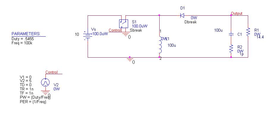
I am doing a boost converter 12V in (battery) 20V out. Just 12W.
It is to go in a metal enclosure which is not connected to earth ground.
Now some of the circuit current will couple to the enclosure (magnetically and capacitively due to stray inductance and capacitance respectively).
-This is bad because the “return” current from the boost converter is then no longer the same as the “go” or “hot” current.
-And in effect we say that pulse currents arise in the supply to the boost –and we call these “common mode” currents –that is “common mode noise”.
Now , can I get rid of this common mode noise by putting some small ceramic caps between the circuit ground and the metal enclosure?
-or will this just produce more common mode currents than before because now there is even more capacitance to the case?
O o o o o o o o o o o o o o o o o o o o o o o o o o o o
In fact, must I actually use a common mode choke at the front (supply terminal) end of my power supply?
More in fact, is it not the case that the common mode choke must be used IN CONJUNCTION with the use of small capacitors connected between the circuit ground and the case ?…
-This way the energy that couples to the case is then “sucked” back into the circuit –-….being “sucked” back via the small capacitors that have been placed between the enclosure and the circuit ground ?
Is this how common mode filtration is done in boost converters inside metal enclosures ?