Continue to Site

Welcome to EDAboard.com

Welcome to our site! EDAboard.com is an international Electronics Discussion Forum focused on EDA software, circuits, schematics, books, theory, papers, asic, pld, 8051, DSP, Network, RF, Analog Design, PCB, Service Manuals... and a whole lot more! To participate you need to register. Registration is free. Click here to register now.

Class AB output transistors region of operation at maximum swing

Status
Not open for further replies.

Junus2012

Advanced Member level 5
Joined
Jan 9, 2012
Messages
1,552
Helped
47
Reputation
98
Reaction score
53
Trophy points
1,328
Location
Italy
Activity points
15,235
Dear all,

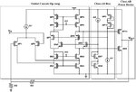
below is the very know to you the class AB OP-amp,

It is by literature or simulation, the output voltage swing towrds rails. However, if we assume that output transistors should be in the saturation region as a condition of operation, then it looks impossible to have rail to rail output swing.

My question, suppose I am using single supply operation with VDD = 3.3 V, and I want the output signal to swing between 0.3 and 3 V,
take now the cade where Vo = Vomin = 0.3 V and prove please that MN9 is in the saturation region,

here is my solution, for MN9 to be in saturation then VDS(sat)(MN9) >=VGS(MN9)-Vthn,,,,

say we are at the border of sat then VDS(sat)(MN9) =VGS(MN9)-Vthn

Subsitute the value of VDS sat(MN9) and Vthn results in VGS <= 0.9 V

to find VGS(MN9) from kirschoff voltage loop at the gate of MN9 to VDD , thus VGS= VDD-VDS sat(MP4)-VDS sat(MP6)- VDS sat(MP8)
if you assume typical values of VDS sat(MP4)=VDS sat(MP6)-=VDS sat(MP8)=150 mV and Vthn = 0.6 V.....then VGS-Vthn =2.25 V

Since 2.25 V is greater than 0.9 V, it means driver transistor MN9 is at triode region even before appraoching the maximum value
buffer.jpg

Thank you in advance

Regards
 

Of course it will not be in saturation. And so what?

Saturation is for voltage gain. M9's role is current
gain / delivery, and as long as it provides conductance
appropriate to the input conditions, and not heinous
crossover / nonlinearity, "region" does not matter.

It's the "Class AB Bias" (and fellow travelers) job
to "make it so".

"Go for saturation unless you have a good reason
otherwise" is a more reasonable philosophy. But
pedants always like to start with bombast and let
grad level courses (or hard knocks) supply more
subtle perspective / approach. Don't get wrapped
around somebody else's axle.

In this case "otherwise" is that, for the function,
operation must be as you say. To get saturation in
a common source output stage with negligible Vds,
your only option would be a depletion mode FET
(not often found in IC technologies, even less
common that it's well modeled or controlled).
 
Dear freebird,

Thank you for your answer,
Indeed I needed this confirmation and you explained it well,

It is not me who want to make the condition of saturation, but the Analog Devices in their manual they linked the Vomax to the VCEsat as they are referring to the bipolar,
The second one is from Huij book, when he tried to calculate the maximum output current of the circuit he assumed the driver transistors are still in saturation, which was the reason I was wandering how it is possible, I think his assumption is wrong and your arguemnt is the right one I will follow

- - - Updated - - -

I forgot,

Is there any difference between output common mode range and output swing ??

- - - Updated - - -

Here is the part from Analog Devices manual, see please how they constrain the output swing to the saturation region

output swing.JPG
 

The output is "rail-to-rail" when there is almost no load current.

Thank you Audi for your reply

The output aswing is always measured or simulated with a connected load, in which means there must be a current to consider
 

Hi,

Is there any difference between output common mode range and output swing ??
Can´t remember ever heared about "output common mode range" on a non_differential amplifier output.

Where do you have this phrase from? Link? Datasheet?

Klaus
 
Output swing is a simple thing. I would consider
output common mode range to be the range
over which output-specific and functional attributes
of interest are within spec table limits.

For example Iout will fail spec before unloaded
output hits rails; AVOL tends to dive as output
approaches rails, stability margin is not to be
assumed, etc. I would say that if a care-about
fails at some point in the output range, you're
outside output common mode range. Just as
with input common mode range (ICMR).
 
Dear friends,

Thank you for your answers regard the OCMR,

Back tothe origional question about the transistor status at the rails,

Here in Holberg, he is assuming the transistors (M6, M7) are still in saturation to define the border of the output voltage swing, it is ok for M7 as it is a current source transistor but how M6 still to be in saturation at Vomax ?

OCMR.PNG

Regards
 

If OPAMP is output rail to rail, in conditions when its output is at rail, the outputs transistors at this rail are not in saturation and they does not need to be.
 
Thank you Dominik for your confirmation...
It is well understood now

Thank you all guys
 

Status
Not open for further replies.

Part and Inventory Search

Welcome to EDABoard.com

Sponsor

Back
Top