Continue to Site

Welcome to EDAboard.com

Welcome to our site! EDAboard.com is an international Electronics Discussion Forum focused on EDA software, circuits, schematics, books, theory, papers, asic, pld, 8051, DSP, Network, RF, Analog Design, PCB, Service Manuals... and a whole lot more! To participate you need to register. Registration is free. Click here to register now.

[SOLVED] Circuit for testing a x-tal

Status
Not open for further replies.
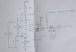
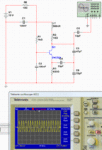
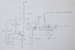
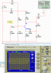
Update:

Rebuilt the circuit with new components , all are none SMD type now, same problem as before, it will only oscillate at the base of the right transistor , about 1.2v, sometimes not, I need to touch the conponets then it starts again. at c112 (supposed to b ethe output , will oscillate hardly if I touch the circuit . I do not have any bias voltage (-5.2v) nor tune voltage attached. Question here, do I realy need the offset voltage and the tune voltage while I am testing the oscillator in a stand alone state ? does the oscillator oscillate without them?
I am using high transition frequency transistors BF959 , also Iam using a 470 nH for the 560 nH , I do not hav ethe 560nH value at my site.
I also tried to shorten the varicap and the 560nf inductor to the left of it to match the simulation diagram. but did not get any oscillations at all.
Regards
George
 
Last edited:

The -5.2V bias is not needed if that part of the circuit is not connected for testing purposes. You can even take the varicap out if you want until you get stable oscillations. Do you have the 1pF cap over the crystal connected? What happens if you increase the 274Ω resistor to say 470Ω? If you use a 470nH then you will have to increase the 33pF cap in the tank. Make it 39pF.

For basic testing to see if the circuit will oscillate you can even remove the crystal and put a 100pF cap in it's place. The circuit should oscillate near 29MHz with a higher output level.

********************************************************

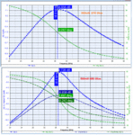
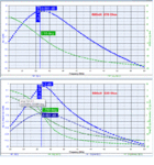
Something troubled me from the beginning about the 560nH value in the tank. I calculated the value need to be around 880nH. I have done some open-loop simulations now, and I can't understand how the circuit will have enough loop gain to reliably oscillate at 29Mhz?

If we look at the plots with using the 560nH and the 270Ω damping resistor, it shows that we don't have enough gain for oscillations to occur.
We need to increase the resistor value to at least 680Ω before we get past the 0dB mark. And then we are way off 29MHz.

With using a 880nH inductor and the 270Ω resistor we are on frequency but also lack the necessary gain. We need to increase the resistor to a minimum of 620Ω to get enough loop gain for any chance of oscillations. With the crystal in the circuit, we will need an extra couple of dB to make up for the insertion losses.

I used BF547 transistor models for the OL analysis.
 

Attachments

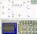
  • 29_test.gif
    29_test.gif
    115.1 KB · Views: 79
  • 29_OL_560.gif
    29_OL_560.gif
    122 KB · Views: 92
  • 29_OL_880.gif
    29_OL_880.gif
    120 KB · Views: 75
Last edited:
  • Like
Reactions: hafrse

    hafrse

    Points: 2
    Helpful Answer Positive Rating
Thaks again fo rthe simulation, I tried to higher the damping resistor (274Ω) to 470Ω and put a 39pF instead of 33pF since I have a 470nH, but still same problem. It seems that the oscilloscope probe kicks the oscillator , it has an internal capcitance of 13pF. It can be a value error (s) in the schemtics.
Regarding changing the 470nH I do have access to capacitors but no chokes. It can be an error in the schemtics (?)

Another track I am thinking about is trying to repair the 29 Mhz osccillator that is in the instrument where it did stoped for some reason, the entire thread started with that I would like to build a clone and Í thought i will be easier since I did not manage to find the fault in the one which is in the instrument, it can be a component which went out of spec. Also, as stated before, the one in the instrument has an older circuit version with one NPN transistor. I wonder why tek has redesignd it since it is little tricky :)

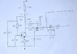
I have managed to drow the circuit now (I think) , I will now use a capacitance meter to measure all the caps and will post the cuircuit on this thread later today.
 
Last edited:

I have now desoldered all the resistors and the cpas from the card, measured all the caps and the resistors, the caps (smd) are measured by a capacitance meter but values around 20pf and down can not be measured by the meter I have.
I tried to locate all the points and the connection, could be something missing, does this circuit looks like a complete oscillator ? could it be a value of cap where it has been changed by age or gone open ? In this design only one transistor is used, tried to locate more components on the card related to the oscillator itself but did not find a connection.

Update: L1 looks like a 560nH (there is an identical one on the board wher it is documented in the schematics).
 

Attachments

  • IMG_3200.JPG
    IMG_3200.JPG
    279.7 KB · Views: 83
Last edited:

Check it again. Something does not look right around the connection of the coil.

What model SA is this from? Is this out of a Tek 2780?
 
Last edited:
  • Like
Reactions: hafrse

    hafrse

    Points: 2
    Helpful Answer Positive Rating
Hello,

You are right, corrected now.
Thanks
 

Attachments

  • IMG_3207.JPG
    IMG_3207.JPG
    247.7 KB · Views: 76

It may be a lazy crystal that is causing the start-up problem. Look at this thread https://www.edaboard.com/threads/114144/ where I posted a circuit of a crystal checker. It worked to over 20MHz. If you lower the value of the 180pF caps to say 100pF it should cover 29MHz with ease. The transistors can be any general purpose like 2N2222, 2N3904 etc.
 
  • Like
Reactions: hafrse

    hafrse

    Points: 2
    Helpful Answer Positive Rating
HJello,

Tried a 26 Mhz crystal, same problem. Will look at the thread you gave me. Thanks
 

Does the circuit oscillate with the crystal shorted out?
 
  • Like
Reactions: hafrse

    hafrse

    Points: 2
    Helpful Answer Positive Rating
Hello,

I tested the circuit with the two transistors, it oscillates with a frequency of 29.82Mhz the same problems as with the crystal. The circuit with one transistor is not re-assembled yet, all the caps smd:s are desoldered for testing. Shall I test the circuit with the one transistor with the x-tal installed ? I will solder the components now.

Thanks for your help!
 

Both of these circuits should oscillate quite easily with the crystal shorted out. If it doesn't then it will most probably not oscillate with the crystal in circuit as it introduces more losses in the circuit. You will have to find out what faulty component prevents oscillations when you have the crystal shorted out.

Can you measure all the DC voltages on the transistors with the crystal removed from the circuit? (removed not shorted out)

Below is a simplified circuit operating with the crystal shorted out.
 

Attachments

  • 29_test_short.gif
    29_test_short.gif
    78.4 KB · Views: 72
  • Like
Reactions: hafrse

    hafrse

    Points: 2
    Helpful Answer Positive Rating
Hello,

Resoldered the caps on the one transistor circuit, crystal shorted, no oscillations. will measure the dc voltages crystal out ont shorted. and get back to you.

- - - Updated - - -

Hello,

Measured in the instrument:
B=+3.4V
C=+9.9V
E=+2.7V

Vtune= +3.70V (cathode of the varicap)
Bias =-5.8V (anode of the varicap)

Crystal is out not shorted

- - - Updated - - -

As I said, caps that are under 30/25 pf can not be measured by my tool, so not sure if thy are ok or they are over that value but are open. What vaules do you think are relevant in my dorwing for C2 ? it was hard to measure it, it gave 0.04nF on the meter but not sure if that is correct, and I stated that it was 0.004uF in the diagram by mistake, sorry for that . Also C3 and C5 should be 33nf (.033)
- - - Updated - - -

- - - Updated - - -

Corrected drowing regarding the caps values C2,C3,C5 and C1:
 

Attachments

  • IMG_3209.JPG
    IMG_3209.JPG
    238.4 KB · Views: 73
Last edited:

Have you tried to just replace the small value caps that you can't measure? That may fix your problem. I would expect C2 to be about 47pF. I would have suspected C1 to be equal or a bit smaller than C2, like in my last diagram.

I think it is important to see if the existing circuit will oscillate with the crystal shorted out. It should. If not, replace all the small value caps and check again.
 
Last edited:
  • Like
Reactions: hafrse

    hafrse

    Points: 2
    Helpful Answer Positive Rating
Will do that,

Caps that I can not measure are :

C10
C11
C2
C4 (1 pF ?)

What values should I use for them ?

Regarding C2 , you mention that C1 to be equal or a bit smaller than C2, C1 is measured to be 33nF and C2 can not be measured (low value or ?).

Thanks
 

What is the value for R3, 10k? DC voltage on the base seems too low for R3 = 10k. Make sure about this value and check that the 0.1uF (C6) on the base is not leaky. Base voltage should be above 8.5V. Make sure R10 is 820Ω

On the other hand if there is something wrong with the transistor and it is not turning on correctly, the base voltage will drop to such a low value.

You can see from the example that if the collector is connected and transistor is working normally the base current is 94uA. When we disconnect the collector the base current increases to 860uA and we drop almost all the voltage over the base resistor.
 

Attachments

  • 29_DC.gif
    29_DC.gif
    14.4 KB · Views: 76
Last edited:
  • Like
Reactions: hafrse

    hafrse

    Points: 2
    Helpful Answer Positive Rating
Hello,

There is a 5.6K resistor from the base to the ground also, missed that, will replace the .1 cap and check the resistor of R10 . updated the diagram.
 

Attachments

  • IMG_3210_1.JPG
    IMG_3210_1.JPG
    282.8 KB · Views: 71

Updated values for C3, C5 and C1, unit was wrong in the last diagrams. Updated diagram :
 

Attachments

  • IMG_3211.JPG
    IMG_3211.JPG
    240.4 KB · Views: 77

The DC values look more realistic now. Put a 330pF cap in place of the crystal like in my diagram below. Circuit should oscillate around 29MHz. If not, you will have to find the faulty part which will most probably be a capacitor as you changed the transistor already.

Once you get it oscillating without the crystal it should work at the exact crystal frequency with the crystal back in the circuit.
 

Attachments

  • 29_test_cap.gif
    29_test_cap.gif
    81.2 KB · Views: 74
Last edited:
  • Like
Reactions: hafrse

    hafrse

    Points: 2
    Helpful Answer Positive Rating
Hello,

You are right! C6 was bad, after replace, I have a very stable 29Mhz signal with crystal installed!!!!

I want to thanks you very much for your help!!! also want to thanks Betwixt for his help from the beginning!!!
 

Glad you got it working. Hopefully, you learned a lot from the analysis and testing procedures.

I was just about to post the waveform I measured after testing the circuit myself today. I had to increase the 47pF to 56pF for oscillations with my 27. 265MHz CB radio test crystal to start reliably. It may be due to the parameters of the crystal I was using. I used a 680nH coil in place of the 560nH. The circuit is very sensitive to probe loading on the collector of the transistor. A much better spot for probing is at the capacitive tap point (over the 330pF cap). The waveform below was measured at this point.

It is interesting to note the time-lapse from switch-on until steady-state oscillations conditions are reached. This is the reason why many circuit simulators have problems with crystal oscillator circuits. The needed 36mS of simulation time on a PC can take many minutes depending on processor speed, memory and minimum step size. If you are not aware of this, you may think the circuit is not working. There are a few tricks to speed it up, but that involves lowering the Q of the crystal quite a bit.
 

Attachments

  • scope_1.gif
    scope_1.gif
    45.4 KB · Views: 75
  • scope_2.gif
    scope_2.gif
    52.4 KB · Views: 77
Last edited:
  • Like
Reactions: hafrse

    hafrse

    Points: 2
    Helpful Answer Positive Rating
Status
Not open for further replies.

Part and Inventory Search

Welcome to EDABoard.com

Sponsor

Back
Top