abomin3v3l
Junior Member level 1

Brian. I connected a capacitor from colletor to ground. New schematic is attached.
I have some doubts:
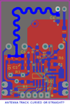
(1) What shape of antenna of the of the pictures is better? curved or straight? Or do you recommend to try both?
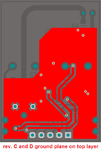
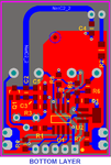
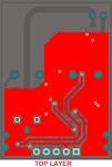
(2) Do I need to place ground plane (red) where the components of the RF amplifier are placed? It is only where the antenna track is that I don't need to place ground plane? Ground plance seems to be correct in your view?
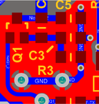
(3) From where to where do I need to connect the twist capacitor? From collector do GND? I think I will try it using my current board... I have thin enameled rigid wire here with 0.6 or 0.8mm of diameter. I use the same wire as the antenna of the receptor, currently I'm using its lenght as 1/2 of wavelenght of 433MHz, around 34.6mm.
(4) Do you know if the meter of your link measures capacitors of few pF? **broken link removed**
(5) I understood your calculations of XC.


