Continue to Site

Welcome to EDAboard.com

Welcome to our site! EDAboard.com is an international Electronics Discussion Forum focused on EDA software, circuits, schematics, books, theory, papers, asic, pld, 8051, DSP, Network, RF, Analog Design, PCB, Service Manuals... and a whole lot more! To participate you need to register. Registration is free. Click here to register now.

Charge pump and single pulse creator, how to?

Status
Not open for further replies.

Attachments

  • circuit2.PNG
    circuit2.PNG
    41.6 KB · Views: 129

The current will be significantly higher for a few cycles and the circuit relies on a low input impedance, if you remove the capacitor the ESR of the cell will play a big part in circuit efficiency and tiny cells have a big ESR! Remember that you are trying to double the voltage to the LED and even if the circuit was 100% efficient, you would have to double the input current to achieve that.

The FET design won't work i'm afraid, firstly it needs the supply to be higher than the LED forward voltage and the knee voltage of the FET, secondly - works in reverse! the LED lights when the switch is opened, not closed!

Brian.

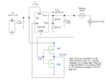
I think this is a better one that does what I want.
When the unit is shaken the vibraswitch closes, the led lights up (since Vout at the mosfer switch is 1) and the capacitor at the gates, is charged.
The high R value gate to ground resistor prevents significant voltage drop during charging.
As long as this capacitor charges Vout is pushed to low and charge pump is disabled, so further shaking of the unit does not light the led.
After a few time of inactivity the capacitor at the gates slowly discharges through the gate to ground resistor and the cycle repeats.

This has an advantage that power is not drawn by the battery at all, even on chip disable, since it is disconnected by the vibraswitch anyway.

Obviously some tweaking with the gate capacitor/resistor values should be done. Any suggested values for say a vew seconds charging and then a minute or so cut off?

Also, any suggestion about the SMD fets to use? 2n7002...?

I also wonder, why can't I use a single fet and replace the top Pfet with a resistor instead?
 

Attachments

  • circuit2.PNG
    circuit2.PNG
    44.7 KB · Views: 132
Last edited:

Hi there,

I thought the switch looked on a strange side given the requirements before the modification. Anyway, glad you've got a viable solution, good for you.

Problem with time constant is that charging and discharging are same, unless you try the 555 duty cycle greater/lower than 50% trick for very low duty cycle on pulse by using a second resistor and place a diode across it, so cap discharges quickly and charges slowly (long off, short on).

A few seconds on is easy, but a minute off may require large cap or very, very preferably large value R ("cursed" cap leakage, etc.), you'll have to do the repetitive sums :) of T = R ohms * C in Farads ( and then tweak the results that don't ever seem to pan out in real world application!)

Isn't it something like 1M and 1uF is 1 second?
 
  • Like
Reactions: neazoi

    neazoi

    Points: 2
    Helpful Answer Positive Rating
Hi there,

I thought the switch looked on a strange side given the requirements before the modification. Anyway, glad you've got a viable solution, good for you.

Problem with time constant is that charging and discharging are same, unless you try the 555 duty cycle greater/lower than 50% trick for very low duty cycle on pulse by using a second resistor and place a diode across it, so cap discharges quickly and charges slowly (long off, short on).

A few seconds on is easy, but a minute off may require large cap or very, very preferably large value R ("cursed" cap leakage, etc.), you'll have to do the repetitive sums :) of T = R ohms * C in Farads ( and then tweak the results that don't ever seem to pan out in real world application!)

Isn't it something like 1M and 1uF is 1 second?

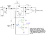
Here is a simpler version that I think will work just like the first one with a single mosfet. It has a glitch though. When the transistor is ON and the vibraswitch is off, the gate capacitor would be discharged not only through the gate to ground resistor, but also through the gate to drain resistors combination to ground. So a little bit of tweaking of these values is required to ensire desired charging/discharging times.
I may benefit from this however. I could remove the gate to ground resistor and discharge the capacitor through the gate to drain resistors combination to ground untill the transistor is on. Why should I need the capacitor to be fully discharged after all? Experimenting will show which way is better.

Yes I was thinking 1M for the gate to ground resistor as well. For a fast charge the gate to Vin resistor must be low, but not so low to blow up the fet. Any suggestion for a starting value?
Also is the 2n7000 suitable for it and what are the threshold levels? (on/off)
 

Attachments

  • circuit2.PNG
    circuit2.PNG
    25.6 KB · Views: 109
Last edited:

The datasheet says VGS(th) 0.8 - 3V, so is the glass half full or half empty? Unprofessional and bad science is guessing lower VGS(th) at the voltage and currents you are using.

Regarding avoiding magic smoke, I really don't know, "Zero Gate Voltage Drain Current" parameter is at (VDS = 48 Vdc, VGS = 0) says 1uA or 1mA, can't see anything about Gate On current in there, and I don't understand that, sorry. More bad science would be calculating expected current based on voltage and different resistor values until you find one you are comfortable using that is safe, until some-one wiser explains how to do that part.

"Yes, it can be done!" is on page 10, if wanted:

View attachment Signetics555556Timers.pdf

If using 1M, then MAYBE the other as 10k or even 100k is safe and suitable for fast charge?

Wouldn't the two resistors in parallel need to be duly calculated to avoid my kind of newbie mistake of "Oh, the 10k is now only 1 ohm as it is in parallel with x resistor!"
 
Last edited:
  • Like
Reactions: neazoi

    neazoi

    Points: 2
    Helpful Answer Positive Rating
That's an old data sheet!

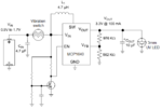
the problem with the '555 solution is that it requires at least 4.5V to operate properly, Neazoi needs it to work at a minimum voltage of 0.9V, far too low for a 555 and only about half of what is needed to light an LED. Some kind of voltage increasing is needed, either with a boost converter as shown or a charge pump.

I have reservations about the schematic, the principle seems to be to generate a one-off pulse at the EN pin when the vibration sensor closes. As the gate capacitor charges it makes the MOSFET conduct, pulls the EN pin low and shuts down the MCP1640. I see several problems, the MOSFET is unlikely to conduct with a Vgs of less than 0.9V and the time it takes to charge the gate capacitor would probably be less than the sensor switch is closed for. I'm guessing the vibration sensor is a standard 'weight inside a spring' type which produces pulses typically < 1mS. Given the time constant at the gate pin and the time it takes to 'pump up' the voltage, there may not be enough time to generate enough voltage for the LED to light.

I think a charge pump with a monostable would work better. I have searched for my spare marker box but unfortunately, I can't find it. It uses an astable charge pump with about 1 second time constant. The principle is to charge a capacitor through a fairly high value resistor so the peak current is kept low. When triggered by a pulse from the vibration sensor, the monostable 'flips' and re-routes the capacitor connections so it appears to be in series with the battery instead of across it. The combined battery and capacitor voltage (~ 2 x Vbattery) is applied across the LED to flash it. The circuit then returns to stable state and recharges the capacitor again. Not only does it only require a brief signal from the sensor to start it, the current it draws in stable state is very low, being almost entirely the leakage current in the charge capacitor (< 1uA).

Brian.
 
  • Like
Reactions: neazoi

    neazoi

    Points: 2
    Helpful Answer Positive Rating
I think a charge pump with a monostable would work better. I have searched for my spare marker box but unfortunately, I can't find it. It uses an astable charge pump with about 1 second time constant. The principle is to charge a capacitor through a fairly high value resistor so the peak current is kept low. When triggered by a pulse from the vibration sensor, the monostable 'flips' and re-routes the capacitor connections so it appears to be in series with the battery instead of across it. The combined battery and capacitor voltage (~ 2 x Vbattery) is applied across the LED to flash it. The circuit then returns to stable state and recharges the capacitor again. Not only does it only require a brief signal from the sensor to start it, the current it draws in stable state is very low, being almost entirely the leakage current in the charge capacitor (< 1uA).

Brian.

I would definitely want tro try this.
Pleae try to find the schematic for it in your spare time.
 

That's an old data sheet!

the problem with the '555 solution is that it requires at least 4.5V to operate properly, Neazoi needs it to work at a minimum voltage of 0.9V, far too low for a 555 and only about half of what is needed to light an LED. Some kind of voltage increasing is needed, either with a boost converter as shown or a charge pump.

An oldie but a goodie...! Have to pay homage to the Swiss watchmaker at any opportunity... I really meant not using a 555 as well, but only the RC with the bypass diode, it was for the example. Your idea is obviously one that works for Neazoi's circuit, so thank goodness for an informed and constructive opinion.
 

Don't know if this is what you're looking for... Just to show what's possible with the joule thief...

Starting with the typical design, add a capacitor in the bias circuit. It discharges slowly. A cycle begins when it drops to a certain level. This recharges the capacitor.


By changing capacitor/resistor values, you can get longer timing cycles. Also reduce current draw from the battery.

- - - Updated - - -

The above circuit was in a website article, '8 year joule thief'.

Notice that the supply is 0.8V.
 
  • Like
Reactions: neazoi

    neazoi

    Points: 2
    Helpful Answer Positive Rating
It's worrying - but I had a thought!

I haven't tried this and I'm rather too busy to build anything at the moment but maybe you can try it:


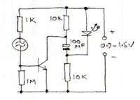
I can't think of a simpler method. The theory is the capacitor charges slowly through the two 10K resistors until it reaches battery voltage, the LED has insufficient voltage across it to conduct and the transistor has no bias current so the circuit stops drawing any current (except leakage). When the vibration switch closes, it passes enough current to saturate the transistor which brings it's collector voltage close to 0V, this makes the negative side of the capacitor go to the battery voltage below 0V so the total voltage across the LED is momentarily twice the battery voltage making it flash.

The 1M resistor is just to desensitize the input to static and help to reduce transistor leakage, it might be possible to omit it. It may also be necessary to add a resistor in series with the LED to limit it's current, especially if a higher value capacitor is used. A transistor with low VCEsat will work best, if it's one with low gain the bias resistor can be reduced down to maybe 100 Ohms.

Brian.


This is very interesting and no transformers/coils are required!
I worry if the battery goes to 1v or so, there may nod be enough output voltage to drive the 3v LED.
Any propositions for the transistor type to try? MPSA18, 2N2222, BC549 or other common types?
 

I did an experiment and the circuit works fine as a voltage doubler but the only UV LED type I have to hand has a Vf of 3.3V @10mA so predictably it only worked down to a supply of ~1.6V.

I tried adding an additional RC stage betwen the transistor and LED, coupled to the original with a small Schottky diode to make it a voltage tripler but because of the additional diode drop it only reduced the minimum working voltage to about 1.4V. This is a classic case of diminishing returns as more stages are added so there was no point in trying a quadroupler circuit.

If you could use a coin cell (CR3032 etc) which has a terminal voltage of about 3V, it would work well and the capacitor recharge time prevents it re-triggering too quickly.

Brian.
 
  • Like
Reactions: neazoi

    neazoi

    Points: 2
    Helpful Answer Positive Rating
I did an experiment and the circuit works fine as a voltage doubler but the only UV LED type I have to hand has a Vf of 3.3V @10mA so predictably it only worked down to a supply of ~1.6V.

I tried adding an additional RC stage betwen the transistor and LED, coupled to the original with a small Schottky diode to make it a voltage tripler but because of the additional diode drop it only reduced the minimum working voltage to about 1.4V. This is a classic case of diminishing returns as more stages are added so there was no point in trying a quadroupler circuit.

If you could use a coin cell (CR3032 etc) which has a terminal voltage of about 3V, it would work well and the capacitor recharge time prevents it re-triggering too quickly.

Brian.

Thanks a lot for the information Brian!
What kind of transistor did you use, or suggest?
Can you tell how you connect these additional components to the circuit?
Also why you did not use a germanium diode instead for much lower voltage drop?
 
Last edited:

I used a PN2222 (= plastic 2N2222) but only because I had them to hand. The best transistor is one with lowest VCEsat. That means the one with lowest collector voltage when biased to saturation.

The extra stage is identical to the one already shown,
+ ----[10K]----||----[10K]---- -
the existing circuit stays the same except the LED is moved to the new RCR components and the new diode links the old LED cathode connection to the top of the new capacitor.

It works in essentially the same way, both capacitors charge up to battery voltage and when the transistor switch is closed, the path
+ ---LED---|new C|---Diode---|old C|---Transistor--- - becomes the LED current source.
The problem is twofold, firstly the diode drops some voltage across it which becomes unavailable to the LED and secondly, some current flows through the diode all the time. The diode current is small but has the effect of raising the voltage at the negative end of the old capacitor, hence reducing the voltage across it. A Ge diode may help by reducing the drop across it but would also reduce the voltage charging in the first capacitor by the same amount. The diode I used was a BAT85 which drops ~0.4V at 10mA so it isn't far off Germanium anyway.

Brian.
 
  • Like
Reactions: neazoi

    neazoi

    Points: 2
    Helpful Answer Positive Rating
I used a PN2222 (= plastic 2N2222) but only because I had them to hand. The best transistor is one with lowest VCEsat. That means the one with lowest collector voltage when biased to saturation.

The extra stage is identical to the one already shown,
+ ----[10K]----||----[10K]---- -
the existing circuit stays the same except the LED is moved to the new RCR components and the new diode links the old LED cathode connection to the top of the new capacitor.

It works in essentially the same way, both capacitors charge up to battery voltage and when the transistor switch is closed, the path
+ ---LED---|new C|---Diode---|old C|---Transistor--- - becomes the LED current source.
The problem is twofold, firstly the diode drops some voltage across it which becomes unavailable to the LED and secondly, some current flows through the diode all the time. The diode current is small but has the effect of raising the voltage at the negative end of the old capacitor, hence reducing the voltage across it. A Ge diode may help by reducing the drop across it but would also reduce the voltage charging in the first capacitor by the same amount. The diode I used was a BAT85 which drops ~0.4V at 10mA so it isn't far off Germanium anyway.

Brian.
I have built the circuit as well, without the additional doubler and worked fine for 1.5v and up on 3v led.
Why during the capacitor charge time, the capacitor is discharged when the vibra switch is closed, before the cap is fully charged?
Would it be better (in terms of power saving) for the capacitor to keep charging without any effect from the transistor during that charging time?
Then only when the led conducts (cap fully charged) the cycle will begin again.

What I mean is that with this circuit, when the vibraswitch is closed and the capacitor discharges, then the next closes of the switch will cause the transistor to draw current from the battery through the collector resistor. Would that be better to prohibit this current to flow somehow and wait until the capacitor is fully charged?
 
Last edited:

You are quite right but I assume the vibraswitch could operate at any time if the device was in motion. The only way to prevent 'early triggering' is to add a timing element to the circuit but it would have to be powered all the time to be sure it inhibited triggering until full charge was reached.

To some degree you could limit the rate at which the trigger could be repeated by altering the circuit at the transistor base pin like this:

(+) ---[100K]--- A ---|100uF|--- (-)
with 'A' connected to a 100 Ohm resistor then through the vibraswitch to the base.

In other words, instead of directly triggering the base from the + supply, you do it from an RC network that slowly charges to battery voltage. Adjusting the RC values will set the time it takes to prepare for enough base current while the switch is open. Ideally you would use a fixed timer to prevent repeated triggering within the time it takes for the boost capacitor to charge up but it would be difficult if not impossible to stop the timer drawing current all the time and draining the battery.

Brian.
 
  • Like
Reactions: neazoi

    neazoi

    Points: 2
    Helpful Answer Positive Rating
You are quite right but I assume the vibraswitch could operate at any time if the device was in motion. The only way to prevent 'early triggering' is to add a timing element to the circuit but it would have to be powered all the time to be sure it inhibited triggering until full charge was reached.

To some degree you could limit the rate at which the trigger could be repeated by altering the circuit at the transistor base pin like this:

(+) ---[100K]--- A ---|100uF|--- (-)
with 'A' connected to a 100 Ohm resistor then through the vibraswitch to the base.

In other words, instead of directly triggering the base from the + supply, you do it from an RC network that slowly charges to battery voltage. Adjusting the RC values will set the time it takes to prepare for enough base current while the switch is open. Ideally you would use a fixed timer to prevent repeated triggering within the time it takes for the boost capacitor to charge up but it would be difficult if not impossible to stop the timer drawing current all the time and draining the battery.

Brian.

Do you think the extra timing network would worth the effort?
We are trying to save battery life at maximum by prohibiting all other currents during the 100uF capacitor charge. The time it takes for this cap to charge is our "main timing".
By including an extra capacitor at the base, we introduce a second timing circuit which tries to follow the main timing. It will work, but current will not be saved, as it will be used to charge this second timing capacitor.So it is a bit of a "cat chasing it's tail" job I think?

Unless the charging resistor is of high value, so that little current is drawn for longer time, which might save power by prohibiting higher current shorter repeat duration, to be drawn from the main timing circuit.


I was thinking of a zener diode connected somehow, but at these low voltages it seems really difficult.
 

Again, you are right but the charging current will be only a few uA and only for a few seconds. Charging and discharging a capacitor into the LED probably uses less current overall than periodically switching an inverter circuit on to keep the capacitor 'topped up'. I'll keep thinking on this, I'm sure there is a way to multiply the voltage by 4 (0.9V -> 3.6V) without drawing current until necessary. Possibly a 'Joule Thief' kind of circuit with timed bias so it shuts down after a few mS then inhibits further triggering for a while.

Brian.
 
  • Like
Reactions: neazoi

    neazoi

    Points: 2
    Helpful Answer Positive Rating
Again, you are right but the charging current will be only a few uA and only for a few seconds. Charging and discharging a capacitor into the LED probably uses less current overall than periodically switching an inverter circuit on to keep the capacitor 'topped up'. I'll keep thinking on this, I'm sure there is a way to multiply the voltage by 4 (0.9V -> 3.6V) without drawing current until necessary. Possibly a 'Joule Thief' kind of circuit with timed bias so it shuts down after a few mS then inhibits further triggering for a while.

Brian.

Thank you very much!
If you find anything please post it here.
 

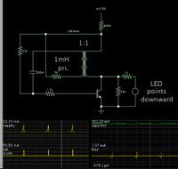
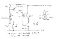
Here's my Mk3 version.

Using the same UV LED (Vf = 3.3V) it gives a bright flash at 0.9V supply with a 'just works reliably' supply voltage of 0.65V. I tried it up to 1.5V but not higher, it should be OK up to about 2V before the LED starts to draw it's own current.

I salvaged the ferrite core from a broken CFL, it seems to be used quite commonly in many different types but I do not have it's specifications or part number. You can get a slight increase in brightness by adding a 100nF capacitor from the junction of the 100R resistor and transformer to ground but it probably isn't worth fitting and it could risk the circuit self-biasing, in other words not shutting down after it has been triggered. It was OK for me but make sure it stops drawing current after a few seconds if you add it to your build. Increasing the 1M timing resistor will make it take longer to re-trigger but don't drop it below about 220K as it pass enough current to turn the first transistor on whenever the switch is closed.

Brian.

 
  • Like
Reactions: neazoi

    neazoi

    Points: 2
    Helpful Answer Positive Rating
Status
Not open for further replies.

Similar threads

Part and Inventory Search

Welcome to EDABoard.com

Sponsor

Back
Top