Continue to Site

Welcome to EDAboard.com

Welcome to our site! EDAboard.com is an international Electronics Discussion Forum focused on EDA software, circuits, schematics, books, theory, papers, asic, pld, 8051, DSP, Network, RF, Analog Design, PCB, Service Manuals... and a whole lot more! To participate you need to register. Registration is free. Click here to register now.

Calculation of circuit components of a Continuous-Time Delta-Sigma Modulator

Status
Not open for further replies.

dragonfury

Member level 4
Joined
Apr 21, 2007
Messages
69
Helped
1
Reputation
2
Reaction score
1
Trophy points
1,288
Activity points
1,724
schreier.png

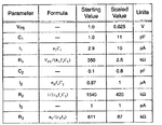
In his book "Understanding Delta-Sigma Data Converters" Richard Schreier has presented a CT Delta Sigma Modulator in Chapter 9 as an example. In this example he has calculated the size of the components of the modulator in Table 9.6 CTMOD2 Circuit parameters as also attached here.

Can anyone help me in understanding that why has he used only Fs as the frequency, whereas if we write the transfer function of the filter is
Vout/Vin = 1/sRC , where s=jw, and w=2*pi*Fs

so where is the 2*pi factor in the table (where the formula) are mentioned?
 

Status
Not open for further replies.

Part and Inventory Search

Welcome to EDABoard.com

Sponsor

Back
Top