Continue to Site

Welcome to EDAboard.com

Welcome to our site! EDAboard.com is an international Electronics Discussion Forum focused on EDA software, circuits, schematics, books, theory, papers, asic, pld, 8051, DSP, Network, RF, Analog Design, PCB, Service Manuals... and a whole lot more! To participate you need to register. Registration is free. Click here to register now.

building lm2596 dc dc using Arduino uno

Status
Not open for further replies.

johnny78

Full Member level 5
Full Member level 5
Joined
Jun 28, 2017
Messages
270
Helped
1
Reputation
2
Reaction score
5
Trophy points
1,298
Visit site
Activity points
3,469
hi Guys
i need to use an MCU as a voltage regulator
read about pwm & checked for some projects on the net
would you check this please ?
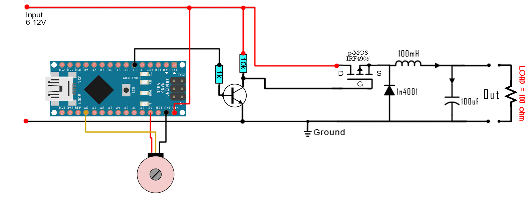
Schematic_NO_feedback.png

first i think the mosfet is connected wrong way (or im wrong) ?
after correcting the connection(S is the input & D is the output) & upladed the simple pwm code to my UNO
& build the citcuit on 3A dc dc buck conveter which i have removed the lm2596 & connected the IRF4509 on it
but it didt work as a regulator


& tried to drive the mosfet with arduino uno with this code
Code:
/*
 * This is an example code for a BUCK converter circuit made with arduino
 * I've used arduino NANO. We have to set the timer of the PWM on pin D3
 * No feedback is connected here
 * Subscribe: http://www.youtube.com/c/electronoobs
 * webpage: http://www.electronoobs.com/eng_circuitos_tut10.php
 */

int potentiometer = A0; //From the main potentiometer
int PWM = 3;         


void setup() {
  pinMode(potentiometer, INPUT);
  pinMode(PWM, OUTPUT); 
  TCCR2B = TCCR2B & B11111000 | B00000001;    // pin 3 and 11 PWM frequency of 31372.55 Hz
}

void loop() { 
 
  float voltage = analogRead(potentiometer);
  int VALUE = map(voltage,0,1024,0,254);
  analogWrite(PWM,VALUE); 

}
 

I would guess the inductor is marked 470 meaning 47 * 10^0 or 47uH.

You must understand the principle of using PWM is that the voltage is recovered from the average of the waveform and adjusting the on to off ratio directly controls the average but in the case of a voltage regulator the situation is a little different, you are controlling stored energy in the inductor. Also understand that the real LM2596 uses a bipolar series switch, not a MOSFET and the drive requirements are quite different between them, in particular the voltage needed between the output and base/gate which depends on what the actual output voltage is and the speed at which they allow their base/gate to change for a given drive current.

Brian.
 

Hi,

You need to understand that your circuit has a completely different behaviour than a true LM2596 circuit.
* different frequency
* different turn OFF timing
* feedbacked vs non feedbacked ...
* different part values
* different reaction time
* analog vs digital
* and so on

so you simply can´t compare it with a true LM2596 circuit.

The impact of "non feedbacked" vs "feedbacked" is like you want to compare an escalator to a car.
The escalator is non feedbacked, always the same speed, doesn´t care about load.
Where with a car you continously have to adjust speed..

Klaus
 

I would guess the inductor is marked 470 meaning 47 * 10^0 or 47uH.

You must understand the principle of using PWM is that the voltage is recovered from the average of the waveform and adjusting the on to off ratio directly controls the average but in the case of a voltage regulator the situation is a little different, you are controlling stored energy in the inductor. Also understand that the real LM2596 uses a bipolar series switch, not a MOSFET and the drive requirements are quite different between them, in particular the voltage needed between the output and base/gate which depends on what the actual output voltage is and the speed at which they allow their base/gate to change for a given drive current.

Brian.
yes thanks its 47uH
Hi,

You need to understand that your circuit has a completely different behaviour than a true LM2596 circuit.
* different frequency
* different turn OFF timing
* feedbacked vs non feedbacked ...
* different part values
* different reaction time
* analog vs digital
* and so on

so you simply can´t compare it with a true LM2596 circuit.

The impact of "non feedbacked" vs "feedbacked" is like you want to compare an escalator to a car.
The escalator is non feedbacked, always the same speed, doesn´t care about load.
Where with a car you continously have to adjust speed..

Klaus
i got it

trying this circuit is just for testing the voltage regulating method not to build an lm2596
but im using already parts on the lm2596 3A dc dc converter in case im just testing to build something can control the voltage

thanks
Johnny
 

just for testing the voltage regulating method
If you want this, then you need to do this. Regulating. With feedback. And you will see a totally different behavoir.

not to build an lm2596
Read your headline ;-)

*****
If you want simple PWM control (without feedback) then use a halfbridge instead of a high side MOSFET.

Klaus
 

Status
Not open for further replies.

Part and Inventory Search

Welcome to EDABoard.com

Sponsor

Back
Top