Continue to Site

Welcome to EDAboard.com

Welcome to our site! EDAboard.com is an international Electronics Discussion Forum focused on EDA software, circuits, schematics, books, theory, papers, asic, pld, 8051, DSP, Network, RF, Analog Design, PCB, Service Manuals... and a whole lot more! To participate you need to register. Registration is free. Click here to register now.

BJT for the lowest phase noise XTAL oscillator

Status
Not open for further replies.
ulrich rohde bft66

The dc current of the transistor has little to do with the quartz dissipation. The best is to run the transistor at 15% of Icmax for best phase noise (flicker noise). The trick is to run the crystal at about 50uW , and use the crystal as both resonator and filter .

By the way

Low Phase Noise Oscillators: Theory, Design, and Laboratory
Instructor: Jeremy K.A. Everard, BAE Systems/Royal Academy of Engineering Research, Professor, Department of Electronics, University of York, UK.

Everad has published many useful low noise papers, I am not sure what products came out of it
 

oscillator low noise bfr93

N1UL said:
In the DC circuit, the PNP transistor samples the DC current up to some offset, and within the loop gain and bandwidth compensates this. The third transistor act as a temperature stabilizing diode. It inverts the voltage drop at the output, including the noise by -180 deg and feeds it back so canceling these contributions to some high degree

So the goal of the feedback is to not let the noise of the transistor disturb the stable bias condition?

Schmocki
 

bjt jfet noise

So the goal of the feedback is to reduce the the DC fluctuation by a factor 10 000 (80dB), the flicker and related noise of the oscillator transistor under large signal condition and therefore reduce the modulation and up conversion within the bandwidth that makes the oscillator "noisy" .

This is standard feedback theory , Ulrich
 

bipolar transistor crystal oscillator circuit

Nice to see this discussion going on so well with all the input from everyone, especially Ulrich. Keep the same pace.

Well, my crystal oscillator is developing nicely and attached are current results. The basic circuit is attached in one of my previous posts.

Phase noise is more or less good (well obviously not as good as profi products mentioned above). However, I need help on the amplitude noise, which is higher than the phase noise at some offsets. Especially the "hump" at 1M-10MHz is troublesome.

I have no feedback currently. The transistor is BFR93A biased at 10mA. The spuriouses at 1M-10MHz are UKW - FM radio transmitters. Shielding the circuit supresses these peaks. Troublesome are spuriouses at 700-1kHz. I have no idea, where these come from. Perhaps some switcher power supplies in the lab.

Thanks for useful input,
rfmw

PS: I would greatly appreciate some phase-noise measurement plots, since simulation doesn't necessary mean the real thing.
 

bjt oscillator circuit

It is unusual, if not in violation of the laws of physics, that the AM noise should be higher, even that high. My dc feedback cures these problems. Overall a nice oscillator , with attractive low noise. It could be made -140 dBc/Hz at 100Hz offset, this requires some work . See the attached file


Ulrich
 

    rfmw

    Points: 2
    Helpful Answer Positive Rating
oscillators and device ft

Hello rfmw et al.

I think your close-in AM noise is probably better than you realise! The E5052B is noisier on AM than phase noise - with 100Hz start frequency and 100 correlations you are actually seeing the test set's noise over most of the range. If you set a number of correlations and turn averaging off, the nature of the trace tells you whether you are seeing the noise of the DUT alone. Generally if the trace looks 'ragged', the E5052B noise is still significant; if it is thin and smooth, the DUT noise is dominant.

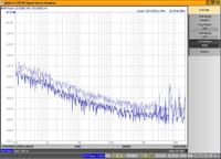
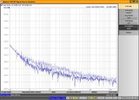
The attached plots show AM and phase noise of a 120MHz OCXO measured over the same offset range, with 100 correlations (faint trace) and 4000 correlations (bold trace).

The AM noise with 100 corr is very similar to your result. 4000 corr gives about 8dB improvement, as expected if the test set's noise is dominant. The indicated AM noise (100 / 4000 corr) is higher than the phase noise because of the E5052B's noise - not the oscillator.

The 4000 corr measurements took 40 minutes for AM and 20 minutes for phase noise. (For lowest noise we generally set the start frequency to 1Hz and set about 4000 correlations, and leave it running all night!)

Garry


  • Like
Reactions: stromer

    rfmw

    Points: 2
    Helpful Answer Positive Rating

    stromer

    Points: 2
    Helpful Answer Positive Rating
super low phase noise reference

Good point and follow up , thanks, Ulrich
 

crystal oscillator bjt

Hi,

I wonder why the noise performance of the E5052's IF amplifier is so bad. -120dbV/Hz @ 1Hz is not what you would expect from such an expensive instrument.

Ok, maybe the slope of the phase detectors is high enough so the IF amps noise does not really matter, and the noise contribution from the local oscillators masks the IF amp's noise.

Schmocki
 

1mhz oscillator circuit bjt

Garrythorp, thanks a lot for pointing this out. As I'm relatively new to the phase noise world, my primary concern was that the SSA's phase noise was under my oscillator's and the AM noise was of secondary importance. Sure, to have a good phase noise, one must have low AM noise as well. My SSA is quite phase noisy between 1kHz to 10kHz as noise drops exactly with the correlation factor when measuring my XCO. This is not the case below 1kHz.

Your oscillator's performance is quite impressive. What is the procedure for achieving phase noise floor below -170dBc/Hz in terms of crystal power, oscillator- transistor output power, buffering, etc? I would expect that your osc. transistor outputs medium to high output level. How do you keep crystal's dissipation to more or less 100-500uW range while at the same time running transistor at high power? Or am I missing something important here?
 

low-ft phase noise

Another interesting point about the E5052B is that its noise at any given offset appears to depend entirely on how long it spends doing correlation, irrespective of the 'number of correlations' you set.

For example, a single phase noise measurement from 10Hz to 20MHz offset takes 2.5s. If you set the start frequency to 1Hz offset, it takes 10s but its noise is 3dB lower - exactly the same as doing '4 correlations' with 10Hz start frequency, so you gain more information without losing out on the measurement time/noise floor figure. It seems to use whatever time it has available, to do as much correlating as possible. Sorry if I'm telling you something you've already discovered!

Re oscillator noise floor: taking the output via the crystal makes use of its bandpass filter action to attenuate wideband noise. Also make sure the buffer amplifier isn't driven into compression, as that can seriously increase its noise. This is all covered in an excellent tutorial presentation by Michael Driscoll, at:
**broken link removed**

Driscoll has been publishing really useful papers on oscillator-related stuff for over 35 years – well worth searching for. (On earlier papers, you will find him under Westinghouse.) Wenzel's web site also has a good library section, with lots of interesting articles.

Garry
 

    rfmw

    Points: 2
    Helpful Answer Positive Rating
xtal osc stability

Excellent link! Thanks a lot.
 

butler oscillator phase noise

Starting from the above information I follow up all the publications that I found about Driscoll (back to sixties), and incredible, seems that he is the father of the true low noise oscillators.
All the new authors just copied him, more or less. My respect!
 

overtone xtal oscillator

Driscoll and Parker (NIST) are amongst the world best in Quartz oscillator design, and the Wenzel products. Both have not yet resorted to the time domain non-linear CAD design and optimization. This is an important task ahead, as to compensate for some of the noise contributions from non linear effects like AM to PM conversion and the flicker noise of the crystal. This will be an interesting task. Who is ready to work on this ?

Ulrich
 

lowest phase noise

I think many of us would really like the opportunity to dig deeper into this material but as always a lack of time, funds and/or good measurement equipment prevents us from doing so.
 

bipolar transistor ft

General comments on noise :

The early oscillator pioneers like Leeson, Driscoll, Healey III , Parker and others did their analysis based on linear assumptions, which do not get the same good results as available today. The modern methods require large signal parameters which Agilent now calls X parameters. Provided that the input parameters for the models are OK, the harmonic balance simulators can tackle this. I prefer measurements , using a network analyzer and then a set of analytic equations. The results for modern planar resonator based oscillators up to 20 GHz are much better then the conventional predictions without dealing with the conduction angle of the current and suppressing or even enhancing certain harmonics

This modern approach, heavily depending on non liner analysis and mathematics shows a further improvement, by reducing the AM to PM conversion, both modulation and conversion noise (close in and far out noises are different in their origin).

It applies both for crystal oscillators and printed resonators and other solutions. I will follow up with a series of IEEE publication and validations , but the curious readers may find the basic presentations useful.
The Design of Modern Microwave Oscillators for Wireless Applications, by Ulrich L. Rohde, Ajay K. Poddar, Georg Böck, published by John Wiley & Sons, New York, NY, May, 2005, ISBN 0-471-72342-8.
 

Might the best transistor actually be two or more in parallel?
 

The theory, at first glance, implies that multiple transistors should give better phase noise. I have seen analog (<1 MHz) low noise opamp circuits like that with 3 darlington pairs at the front end, to achieve < 1 nv/rt-Hz noise. The theory is that the signal currents will add coherently, but the phase noise (or 1/f noise if that is your concern) would add incoherently, which is a 3 dB difference for a pair.

In practice, though, I have never seen it actually work for oscillators. In fact, most medium to high power FETs are actually made up of multiple smaller FETS in parallel, but they don't seem to exhibit a phase noise improvement up and above what Leeson predicts based on NF and Oscillating Power.

Anyone have any contrary results?
 

The parallel configuration of bipolar transistors is found above 2 GHz using smaller transistors. Even at 50 GHz, this works but some stability problems may be observed
 

Yeah, but the question is, if you take the same oscillator and make it first with one transistor, and then a second time with 2 transistors in parallel, is the close-in phase noise 3 dB better with the later case (assumed: keeping resonator Q and total oscillating power the same)?
 

PSI in strangely Perth Western Australia, produce low phase noise Saphire osciilators, instruments etc that rival Wenzel.

eg
The SLOOP range of Sapphire Loaded Cavity Oscillators.
These oscillators represent a new level of affordability in ultra-low phase noise microwave oscillators, with typical phase noise performance surpassing that of the best quartz based signal sources, and exhibiting superbly clean and low far from carrier noise.
Based on PSI proprietary High Q Sapphire resonator technology integrated in a unique Loop Architecture these Sapphire LOOP oscillators drive like a sports car.*
* PSI SLOOP Customer
Phase Noise Offset f(m)
-130 dBc/Hz 1 kHz
-155 dBc/Hz 10 kHz
-173 dBc/Hz 100 kHz
-176 dBc/Hz 1 MHz
For more information see the Data Sheet.
 

Status
Not open for further replies.

Part and Inventory Search

Welcome to EDABoard.com

Sponsor

Back
Top