Continue to Site

Welcome to EDAboard.com

Welcome to our site! EDAboard.com is an international Electronics Discussion Forum focused on EDA software, circuits, schematics, books, theory, papers, asic, pld, 8051, DSP, Network, RF, Analog Design, PCB, Service Manuals... and a whole lot more! To participate you need to register. Registration is free. Click here to register now.

Behaviour of transient response when PM and cross-over frequency changes

Patrick_66

Member level 3
Joined
Nov 18, 2023
Messages
60
Helped
0
Reputation
0
Reaction score
0
Trophy points
6
Activity points
409
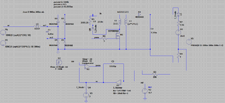
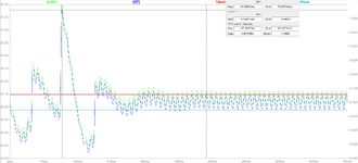
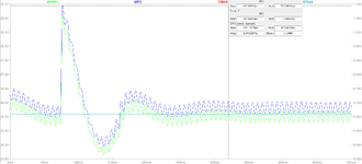
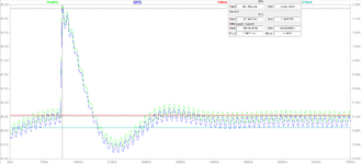
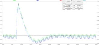
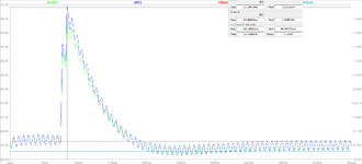
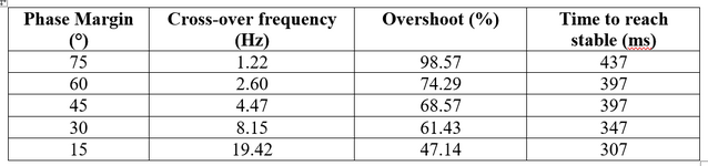
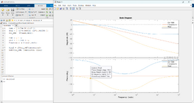
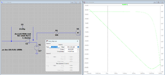
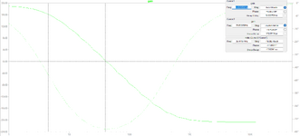
Hello everyone, I'm currently building an LED driver using type one compensation and I simulated the output current with different phase margins and cross-over frequencies to study the response of the system. The result that I got is when the phase margin decreases the cross-over frequency increases and the percentage of overshoot as well as the time to reach transient decreases but the damping increases. Wanted to ask whether this situation is normal? If the result is correct, if possible can you explain why is this situation like this. Thank you in advance and sorry for my ignorance.
 

Attachments

  • LED driver.png
    LED driver.png
    62.5 KB · Views: 44
  • PM=15.png
    PM=15.png
    58.6 KB · Views: 35
  • PM=30.png
    PM=30.png
    54.7 KB · Views: 31
  • PM=45.png
    PM=45.png
    55.7 KB · Views: 34
  • PM=60.png
    PM=60.png
    54.5 KB · Views: 32
  • PM=75.png
    PM=75.png
    54.1 KB · Views: 37
  • Result.png
    Result.png
    29.6 KB · Views: 42
Hello Sir, may I ask why my overshoot keeps on decreasing as the phase margin decreases?

As phase margin decreases overshoot increases. Why yours is doing the opposite I have no clue.

What simulator are you using ? Note it seems your overshoot value is changing very little over
most of the screenshots. How is phase margin being calculated ?


Regards, Dana.
 
Last edited:
Hello Sir, firstly I identify the transfer function of the flyback converter and then identify the transfer function of the compensator circuit then multiply them together to obtain the overall transfer function of the system including the PWM, flyback system and the compensator. Something like the Figures below.
 

Attachments

  • Bode.png
    Bode.png
    156.4 KB · Views: 22
  • Error.png
    Error.png
    79.6 KB · Views: 23
  • TF_Bode.png
    TF_Bode.png
    56.1 KB · Views: 24
When cascading, in order to use simple multiplication of the transforms, they individually have to meet :

When cascading two Laplace transforms, each block must satisfy certain constraints to ensure the overall system behaves as desired. Here are some key considerations:

  1. Causal Systems: Both Laplace transform blocks should represent causal systems. In other words, their outputs should not depend on future inputs. Mathematically, this translates to the regions of convergence (ROC) of their respective Laplace transforms being in the right half-plane (RHP) for stability.
  2. Stability: Each block individually should be stable, meaning their transfer functions should have poles in the left half-plane (LHP) of the complex plane. This ensures that the system's response decays over time rather than grows unbounded.
  3. Linearity: Each block must be linear. This means that the input-output relationship of each block follows the principles of superposition, i.e., scaling and addition.
  4. Causality: The overall system must remain causal. This means that the output of the cascade at any time depends only on past and present inputs, not future inputs.
  5. Compatibility: The Laplace transform of the input and the Laplace transform of the output of the first block must match the Laplace domain input and output requirements of the second block.

So output of each transform must be unperturbed by the loading of the next transform.
In other words the driving transform into the receiving one must be a V source ? Not
expert here.....think buffer between each stage conceptually.


Regards, Dana.
 
When cascading, in order to use simple multiplication of the transforms, they individually have to meet :


So output of each transform must be unperturbed by the loading of the next transform.
In other words the driving transform into the receiving one must be a V source ? Not
expert here.....think buffer between each stage conceptually.


Regards, Dana.
Sorry Sir, I do not quite understand. I'm confused now.
 
Each T(S) must be isolated from each other in order to use simple multiplication
of them to get overall T(s).

1713378734268.png
 

LaTeX Commands Quick-Menu:

Similar threads

Part and Inventory Search

Welcome to EDABoard.com

Sponsor

Back
Top