Continue to Site

Welcome to EDAboard.com

Welcome to our site! EDAboard.com is an international Electronics Discussion Forum focused on EDA software, circuits, schematics, books, theory, papers, asic, pld, 8051, DSP, Network, RF, Analog Design, PCB, Service Manuals... and a whole lot more! To participate you need to register. Registration is free. Click here to register now.

Battery over discharge & other indicator circuit

Status
Not open for further replies.
Re: Battery over discharge & other indicator circuit

sir you said "the 4th one does but its high current does not match your little battery"

In explanation below the diagram , an adjustment option to get required charging current by means of R5 (1k) is there . .
& too my battery current rating is 1 Amp. & 1.0 Ah.
No.
R5 adjusts the output voltage of the LM317 as is shown in its datasheet. R1 is 0.5 ohms so when the current in it that is overcharging the battery creates 0.65V across it then the charging current is limited to 0.65V/0.5 ohms= 1.3A that is MUCH too high for your little battery that charges at about 0.1A.
 
Re: Battery over discharge & other indicator circuit

No.
R5 adjusts the output voltage of the LM317 as is shown in its datasheet. R1 is 0.5 ohms so when the current in it that is overcharging the battery creates 0.65V across it then the charging current is limited to 0.65V/0.5 ohms= 1.3A that is MUCH too high for your little battery that charges at about 0.1A.


hmm thats a fact . . well maximum charging current on battery is given as .21 A

so please suggest a design on the basis of explanations under battery university site

i am not able to find out or design
 

I think the MAXIMUM charging current of your little battery is 0.21A so maybe it will be best to limit the current to 0.167A by replacing R1 with 3.9 ohms/0.25W.
Set the charging voltage to 13.80V and the battery will charge well and be fine.

As it says in The Battery University it is wrong to sense the battery voltage to see if it is fully charged because when the voltage reaches 13.8V then the battery is only about 70% fully charged. If you never fully charge your battery then it will be damaged.
You need a circuit to monitor the charging current and when the current drops low then the battery is fully charged.
Maybe there is a battery charger IC made for your old type of battery like ICs made for new types of batteries.


ooooooooo thats a critical matter i ve to step in . . so as per your opinion should i make a monitor with indicator pack or a simple digital or analog ampre meter ? whats the solution now ?
 
Last edited:

ooooooooo thats a critical matter i ve to step in . . so as per your opinion should i make a monitor with indicator pack or a simple digital or analog ampre meter ? whats the solution now ?
I said that a voltage indicator to show the amount of charge of a lead-acid battery is useless. You must monitor the charging current instead.
 

Re: Battery over discharge & other indicator circuit

ya ya that one that one , how to buld that up ?
1) Select an opamp that has inputs that work at close to its positive or negative supply voltage. Most of these modern opamps are not available in your country.
2) Connect a low-value resistor in series with the supply voltage to sense the current. Maybe this resistor is not available in your country.
3) Connect the opamp so it amplifies the sensed voltage across the resistor that is caused by the charging current.
4) The opamp drives a transistor or Mosfet that disconnects the charger and lights an LED.
You design it or go to school and learn about it.

- - - Updated - - -

Why should I design the circuit for you? I do not know which few parts are available in your country. What can you do for me?
I do not even like old lead-acid batteries.
 
Re: Battery over discharge & other indicator circuit

1) Select an opamp that has inputs that work at close to its positive or negative supply voltage. Most of these modern opamps are not available in your country.
2) Connect a low-value resistor in series with the supply voltage to sense the current. Maybe this resistor is not available in your country.
3) Connect the opamp so it amplifies the sensed voltage across the resistor that is caused by the charging current.
4) The opamp drives a transistor or Mosfet that disconnects the charger and lights an LED.
You design it or go to school and learn about it.

- - - Updated - - -

Why should I design the circuit for you? I do not know which few parts are available in your country. What can you do for me?
I do not even like old lead-acid batteries.


ya simple opamp resistors are available here sir i told you about it
 

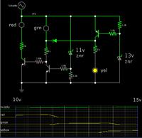
I believe someone at this forum posted this 12V battery monitor.

Three led's indicate battery voltage.
Red = low (below 11.5 V)
Green = normal (11.5 to 14)
Yellow = high (above 14)


Sir , if we apply the same circuit just to monitor

1) 4 volt
&
2) 8 volt

then what changes we need in the component values for both the cases ?
please tell
 

Sir , if we apply the same circuit just to monitor

1) 4 volt
&
2) 8 volt

then what changes we need in the component values for both the cases ?
please tell

An excellent question.

First of all you would reduce the zener values (to about 4V and 7V).

The 1k resistor values will need to be reduced, depending on how bright you want the led's to be.

Most of the resistors will need to be lower values. Their values will need to be adjusted, depending on transistor gain. Operating at these lesser volt levels, small changes will have a greater effect on transistor response.

Falstad's simulator is easy to use. Here is the link which will open his website (falstad.com/circuit), load my updated schematic into his simulator, and run it on your computer.

https://tinyurl.com/mkasqfj

To change values, right-click on a component, and select Edit.

You can read current through an led by hovering the mouse over it.


yeah sir i gone through it !

well i got zener of values 3.9 volts & 6.8 volts

so are they ok for the purpose ?


Too as per your wonderful link of Falstad's simulator

i designed one configuration of stand by level indicator for a

4 volts 1 amp battery of standby use : 4.70 to 4.90 v

by modifying original one , in this way

sample 00.jpg


(above is the snapshot only as i don't know how to export properly)

please check if it require changes . . . thanks :)
 
Last edited:

well i got zener of values 3.9 volts & 6.8 volts

so are they ok for the purpose ?

Too as per your wonderful link of Falstad's simulator

i designed one configuration of stand by level indicator for a

4 volts 1 amp battery of standby use : 4.70 to 4.90 v

by modifying original one , in this way

View attachment 102440

(above is the snapshot only as i don't know how to export properly)

please check if it require changes . . . thanks :)

Yes, your simulation appears workable.

I hope your real zener diodes have the precise value you need. The ones I've seen are manufactured to a 5% tolerance. So your real circuit may need some tweaking.
 
okk :)Too sir please check the circuit in link below :
Another horrible circuit.
It can charge a 1.2V AA Ni-Cad or a "9V" Ni-Cad battery because it does not limit the voltage and it can destroy a modern NI-MH battery. It does not detect a full charge so it keeps on over-charging that can destroy a battery.
 

Another horrible circuit.
It can charge a 1.2V AA Ni-Cad or a "9V" Ni-Cad battery because it does not limit the voltage and it can destroy a modern NI-MH battery. It does not detect a full charge so it keeps on over-charging that can destroy a battery.

He did say, in the OP, it is a sealed lead acid battery.
 

He did say, in the OP, it is a sealed lead acid battery.


ya but instead of starting a new thread i just posted the circuit diagram for a simple check , i got it while googling info. about chargers :)
 

okk :) thanks ! Here "need some tweaking" means ?? what to do ??

You can add to a zener's value by adding a diode, in increments of 0.6V with a silicon diode.

Or by putting a resistor inline. This is a second-best solution of course, since it reduces the abruptness of the zener's effect.

To reduce a zener's value is not so easy. Put a potentiometer across it, and dial to a lesser value. This wastes some amount of current.

You can also use an adjustable zener such as the TL431.
 

Status
Not open for further replies.

Part and Inventory Search

Welcome to EDABoard.com

Sponsor

Back
Top