Continue to Site

Welcome to EDAboard.com

Welcome to our site! EDAboard.com is an international Electronics Discussion Forum focused on EDA software, circuits, schematics, books, theory, papers, asic, pld, 8051, DSP, Network, RF, Analog Design, PCB, Service Manuals... and a whole lot more! To participate you need to register. Registration is free. Click here to register now.

[SOLVED] Automation of AIR CONDITIONER through sensors

Status
Not open for further replies.
It sounds like you just want to automate the AC in one room;

RFID Negatives
- you have to carry the darn thing around - just seems silly to me to find and carry it around so you can 'automate' the AC in one room
- cost, complexity
- if you get short-range you still need a counter or way of detecting direction of egress


PIR has its problems:
- typically covers a wide area, so false triggers are likely [yes you can restrict the coverage, but why bother messing around]
- if done for the room, it will need extra circuitry to handle lengthy periods when you dont move [in your sleep]
 

Dear Kam

I will be using RF Wireless module in which there will be a transmitter which will transmit the status of the number of people in room and receiver will be connected to the AC switch and thus on the status of the received signal it will trigger the AC on or off.
 

hey can anyone suggest me some good book for embedded c programming for atmega 16 controller.
 

Dear Peter

Could you please tell me how to connect my rf transmitter with the controller, I mean should I connect the data pin directly or do I need any current limiting resistance anywhere in its connections....and also what to use as an antenna to connect at antenna pin.

Regards
Ankit
 

All depends what RF module you have.

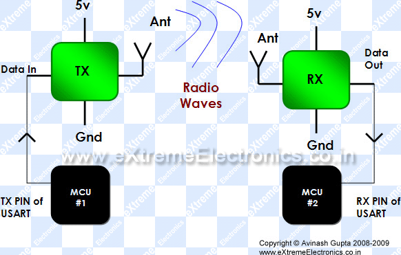
RF Communication Between Microcontrollers – Part I
https://extremeelectronics.co.in/rf/rf-communication-between-microcontrollers-part-i/

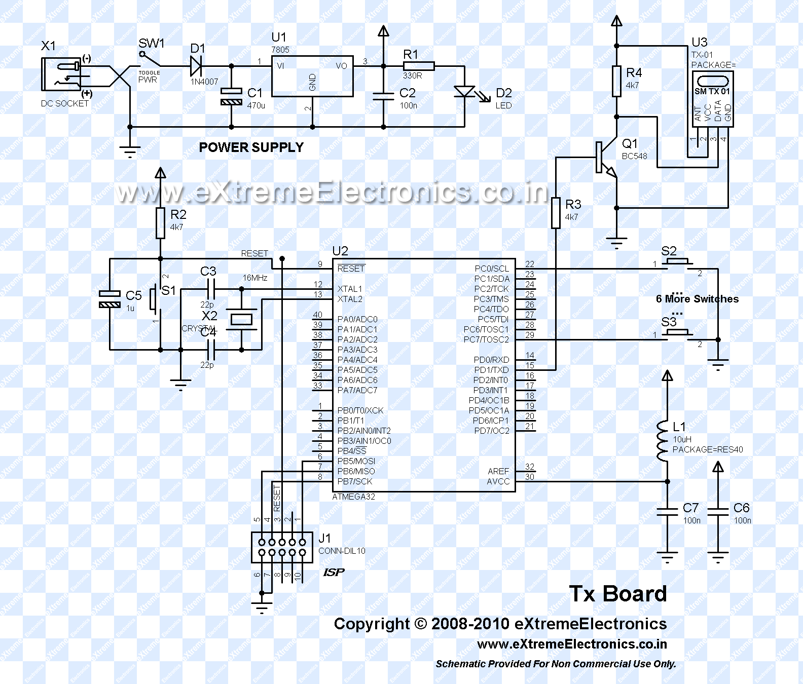
RF Communication Between Microcontrollers – Part II
https://extremeelectronics.co.in/avr-tutorials/rf-communication-between-microcontrollers-part-ii/

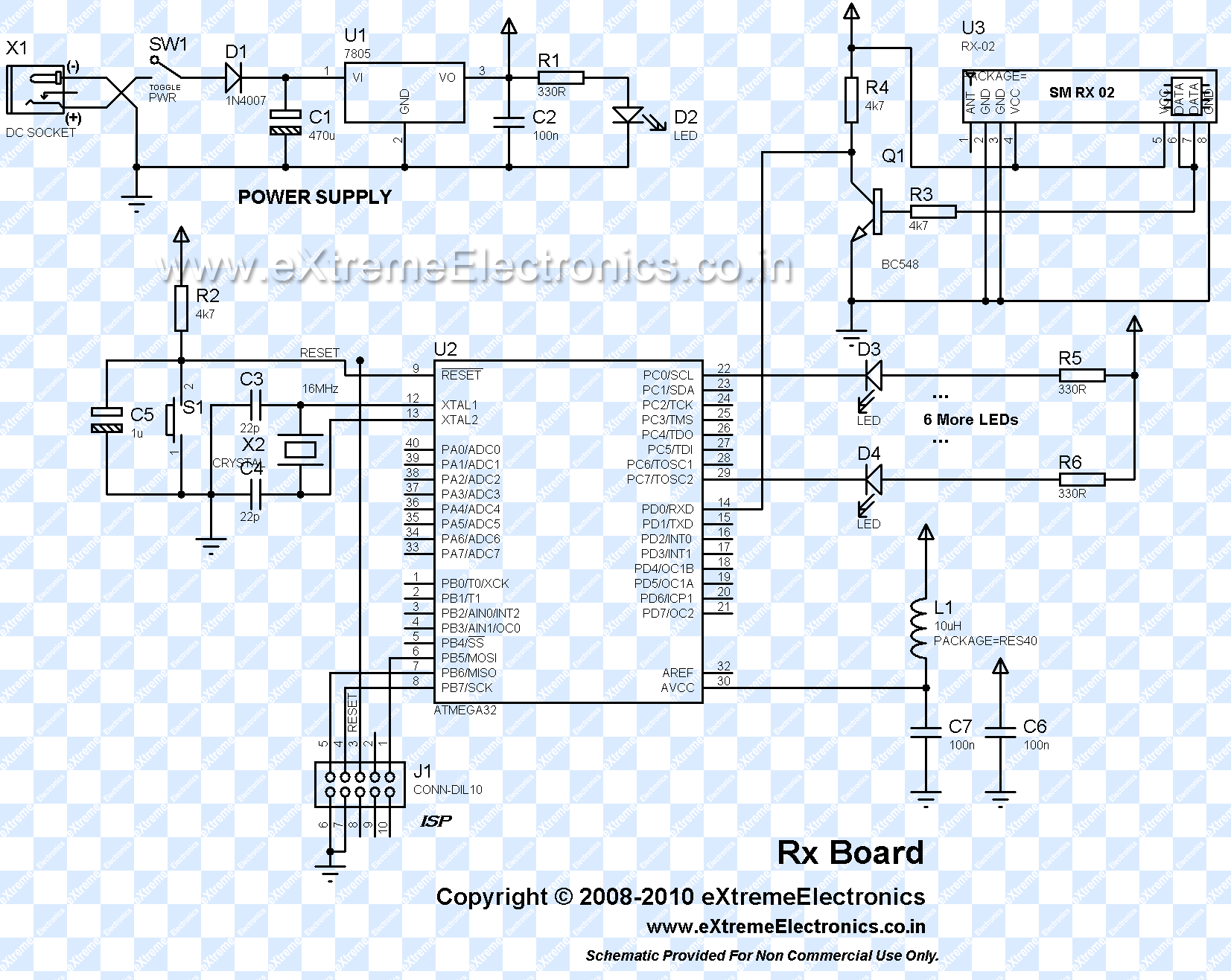
RF Communication Between Microcontrollers – Part III
https://extremeelectronics.co.in/avr-tutorials/rf-communication-between-microcontrollers-–-part-iii/

RF_Module_Microcontroller.gif


RF_Tx.gif


RF_Rx.gif


Best regards,
Peter
:wink:
 

Now supply current should be 2.85 mA, but mu power supply is giving around 500mA, then how to step down it, and will the circuit diagram be same for this module as well?


This can be seen frequently on Internet. I will suggest Ohm Law for start.

Current in circuit is limited with resistance in that circuit.

Your module will use amount of current what he need, what is lower than your psu capabilities.

When you buy a car which can go 250km/h, does the seller said you must drive this car 250km/h ?


Best regards,
Peter

:wink:

Nice way of explaining :razz: so what exactly what you mean is that I need not worry about the current requirements of my module...as suppose my power supplu is giving an output current of 1 A, then also my module will take only what it requires...in our case it is 2.85 mA...... nyways i like your ways of explaining the concepts...Thanxs a lot...:cool:

Regards

- - - Updated - - -

as per my calculations if I want an output current of say 2.78mA, i will be requiring a resistance of value around 1.8K ohms... Am I right peter????

Regards
 

Nice way of explaining :razz: so what exactly what you mean is that I need not worry about the current requirements of my module...as suppose my power supplu is giving an output current of 1 A, then also my module will take only what it requires...in our case it is 2.85 mA...... nyways i like your ways of explaining the concepts...Thanxs a lot...:cool:

Regards

Exactly.


as per my calculations if I want an output current of say 2.78mA, i will be requiring a resistance of value around 1.8K ohms... Am I right peter????

Regards

When you buy RF module they are finished product and they come with declared manufacturers specification. I dont recommend modification of existing RF modules. But when you design your circuit, maybe your RF modules you can calc and use currents what you want. Several things are important for RF modules, modulation type, range, power consumption, size,... Maximum range is not always linked with current and power.


Best regards,
Peter
 
hey peter which programmer do you suggest and which would be most easy to use.

Regards
 

All depends for which microcontroller.

PICKit 2 Clone is nice, you can make it at home for below 10eur, and support lots of Microchip devices. Try to find this programmer you can buy it for small amount of money.

I currently use MikroE MikroProg programmer/debugger he support all Microchip PICs, and its very fast and reliable. I think this is the best for now what exist for PICs.


Best regards,
Peter

;-)
 

I am using atmega 16..

Uh, sorry I didnt pay attention. For AVR you can make cheap USBasp programmer. I use USBasp and I'm satified.


You can use ATMega32 as replacement for ATMega16, if you have trouble to find ATMega16. They are very similar.


Best regards,
Peter

;-)
 
Dear Peter

When you purchase relays, you generally have control over several variables:
The voltage and current that is needed to activate the armature
The maximum voltage and current that can run through the armature and the armature contacts
The number of armatures (generally one or two)
The number of contacts for the armature (generally one or two -- the relay shown here has two, one of
which is unused)
Whether the contact (if only one contact is provided) is normally open (NO) or normally closed (NC)

What does this mean? I mean what will be the values of these parameters for my application. I want to convert the 5 Volt output of controller to 230 VAC, 20A.

Regards


First when you buy relay, you look declared voltage for coil needed for relay to operate. Additional look coil resistance this will determine required current for coil, choose coils with higher resistance.

NO and NC is Normally Open and Normally Connected. Your higher voltage 220V is used on these pins, depending on design.


By the way, 20A at 220V is heavy job for relay, you need to use contactor.


Best regards,
Peter


;-)
 
is interfacing contactor with atmega similar to relay?
 

You can activate contactor using small relay.


Contactor coil can be on various voltages, for example 24V, 48V, 220V.


Best regards,
Peter
 
OKK!! so what you are suggesting me is that First I use a relay, say a relay which gives output of 12 volts and then that relay output terminal is connected to contactor input terminal and contactor output terminal to the load... Isnt it???? will it work????
Something like the attached figure.

Regards
 

Attachments

  • Untitled.png
    Untitled.png
    4 KB · Views: 105

Microcontroller or other control circuit energize small relay coil on 5V/12V, small relay on contacts start contactor coil on 220V, and contactor contacts switch 20A load.


Best regards,
Peter
 
I have written a code for the receiver end with atmega 16


Code C - [expand]
1
2
3
4
5
6
7
8
9
10
11
12
13
14
15
16
17
18
19
20
#include<avr/io.h>
#include<util/delay.h>
void main()
{
DDRA = 0b00000000;
DDRB = 0b00000001;
While(1)
{
    int x = PINA & 0b00000001;  
    If (x = 0b00000001)
    {
        PORTB = 0b00000001;
    
    }
    else
    {
        PORTB = 0b00000000;
    }   
}
}


Please verify the code and i have the attached the circuitry with this code

in this circuit
R and R1 is of 1.8 ohms
and transistor is BC548


Regards
 

Attachments

  • 1.png
    1.png
    13.4 KB · Views: 126
Last edited by a moderator:

Status
Not open for further replies.

Part and Inventory Search

Welcome to EDABoard.com

Sponsor

Back
Top