Continue to Site

Welcome to EDAboard.com

Welcome to our site! EDAboard.com is an international Electronics Discussion Forum focused on EDA software, circuits, schematics, books, theory, papers, asic, pld, 8051, DSP, Network, RF, Analog Design, PCB, Service Manuals... and a whole lot more! To participate you need to register. Registration is free. Click here to register now.

[SOLVED] ATMEGA32 Arduino library osccilator problem

Status
Not open for further replies.

johnny78

Full Member level 5
Full Member level 5
Joined
Jun 28, 2017
Messages
270
Helped
1
Reputation
2
Reaction score
5
Trophy points
1,298
Visit site
Activity points
3,469
hi guys

i need to use the ATMEGA32 for a project but have a problem with Arduino library

i've downloaded this library & it works But the prblem is i have selected (External 16Mhz) as a clock source
& used the blink example to test the chip but the delay is 10x slower
so it blinks almost every 10 seconds instead of 1s
i have removed the crystal but it keeps working
so even the external source is using the internal oscillator

https://github.com/MCUdude/MightyCore

any suggested library or idea will be great or if you have a solution for this issue

thanks
Johnny
 

Hi

I agree with brian.
Lucky you that it works most of the time. But it's surely not reliable.


I don't agree. There always is a reason....

Some rules
* a fast ceramics capacitor at almost each supply pin of each IC.
* a signal is never a one way from A to B, one alwas has to consider the way back from B to A. It is a loop.
im wondering why the MCU uses the wire as a clock ?
check the video with 1 wire to pin XTAL1
* for "switching signals" one has to think about "impedance". Thus thick and wide wires/traces do not improve signal quality. Short traces, small enclosed area in the "signal and return" loop is what counts.
* it's the "edge" that causes high frequency ... and ringing. Thus a 1Hz LED blink signal cuases the same ringing as a 100kHz PWM signal, it´s just multiplied with time.
* especially for not that experienced PCB layouters I recommend to use a GND plane. It reduces all the above mentioned problems.
In your case: to reduce the "loop area" --> just twist all (IN, OUT, GND) wires to the XTAL. It´s still not perfect, but much better regarding EMI, EMC and stray inductance.

Klaus
Hi Guys
Check this video please
i will start to work on this again tomorrow maybe when i get a new ATMEGA32 chip

thanks
johnny
 

Attachments

  • video-1640768855.mp4
    1.3 MB

Hi,
im wondering why the MCU uses the wire as a clock ?
check the video with 1 wire to pin XTAL1
A general rule says:
Don't leave any (unuesd) input floating. (It's as unstable as the flame of a candle in the wind)
This may cause several problems:
* undefined logic level
* increased supply current due to the input stage crowbar current
* increased supply current because of random oscillation
* and in your case: it is likely to pick up any environmental noise (mains frequency, lighting supplies, SMPS, WiFi and other HF subharmonics..)

Klaus
 

You are asking the wrong questions. Instead of asking why does the crystal oscillator "work" with just a wire connected (at whatever frequency), you should ask how to operate it stable at the designed frequency.
 

You are asking the wrong questions. Instead of asking why does the crystal oscillator "work" with just a wire connected (at whatever frequency), you should ask how to operate it stable at the designed frequency.
hi
this was my question of how to set the right Frequency of the crystal because its not clear in Atmel Studio 7
but later i was sharing what's going on

thanks
Johnny
 

Hi Guys
i've got a new ATMEGA32 & started to program it
1st i've tried to select 16Mhz from Arduino list of mighty Core Library but still using the internal oscillator
then i tried to burn the bootloader to the chip but the chip got bricked
luckily i have 2 chips to test on

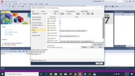
here is the options of Atmel Studio 7 for programming ATMEGA32
i have found the CKOPT but which option should i use of Oscillators?
the fuse Values are

High 0x99
Low 0xE1

in AVR Fuse calculator i have another clearer options
{Ext crystal/resonator HIGH Freq Statup time:16k CK + 64ms {CKSel = 1111 SUT = 11
CKOPT = 0
fuse values are

High 0xC9
Low 0x7F

is this enough to select 16Mhz Crystal ?
i dont want to brick the last chip i have now
so i need your help to make sure of this option

thanks
Johnny
 

Attachments

  • Screenshot (9).png
    Screenshot (9).png
    214.3 KB · Views: 130
  • Screenshot (10).png
    Screenshot (10).png
    245.2 KB · Views: 136

Hi,

When I read post#25 I have more questions than answers.

* when talking about 16MHz ... there are two (or more options): external oscillator, or external chrystal (is internal 16MHz possible?)
* when talking about Arduino ... then often they use a Uart interface combined with a bootloader.
If I'm not mistaken, then fuses can't be set by bootloder / via Uart. But to modify the system clock you have to write the fuses. How is this done exactly?
* when you say "the chip got bricked" .. then most likely when you choose "external oscillator" but use "XTAL" instead. (XTAL usually is a passive device with 2 legs. An oscillator is an active device that needs VCC and GND, CLK is output)

**************
I think in post#25 you are using several methods...I'm mever sure which you use when
* code (executable): arduino, studio, assembler...
* set fuse setup
* uploading the compiled to to the chip (Uart via bootloader, Jtag, ISP via external programmer, ... different PC software)
* uploading the fuses to the chip (programming hardware, PC software..)

Thus I recommend to give use for each trial these informations.

**************

CKOPT is an option for XTAL operation. It selects the oscillation amplitude. Low amplitude for low power, high amplitude when you use the clock additionally on external devices. In doubt activate high amplitude)

Klaus
 

Hi,

When I read post#25 I have more questions than answers.

* when talking about 16MHz ... there are two (or more options): external oscillator, or external chrystal (is internal 16MHz possible?)
no internal 16Mhz
* when talking about Arduino ... then often they use a Uart interface combined with a bootloader.
If I'm not mistaken, then fuses can't be set by bootloder / via Uart. But to modify the system clock you have to write the fuses. How is this done exactly?
first time i used the Mighty core Library i just used the hex file genrated by Arduino IDE & set the fuses by Atmel studio & AvrISP MKII
* when you say "the chip got bricked" .. then most likely when you choose "external oscillator" but use "XTAL" instead. (XTAL usually is a passive device with 2 legs. An oscillator is an active device that needs VCC and GND, CLK is output)
No i didnt choose "external oscillator" & for sure i know what the XTAL is
*************
I think in post#25 you are using several methods...I'm mever sure which you use when
yes i have tried many ways to test
* code (executable): arduino, studio, assembler...
i write code using Arduino then upload it using AvrISP & Atmel studio 7
* set fuse setup
* uploading the compiled to to the chip (Uart via bootloader, Jtag, ISP via external programmer, ... different PC software)
what software you suggest to use with the MKII programmer ?
* uploading the fuses to the chip (programming hardware, PC software..)
AvrISP & Atmel studio 7
Thus I recommend to give use for each trial these informations.

**************

CKOPT is an option for XTAL operation. It selects the oscillation amplitude. Low amplitude for low power, high amplitude when you use the clock additionally on external devices. In doubt activate high amplitude)

Klaus
in AVR fuse calculator :
CKOPT fuse (operation dependent of CKSEL fuses); [CKOPT=0]

So is Cksel 1111 enough ?
or just give me the right fuse settings of using 16Mhz Crystal so i can check it with the datasheet & understand what's wrong with my settings

Johnny
 
Last edited:

Hi,

For the ATMEGA32 to run with 16MHz. (Just from mind, no guarantee to be complete)
* don't use the ATMEGA32"L"
* use clean and stable 5V supply
* use correct XTAL
* use correct capacitors (for XTAL) according XTAL datasheet
* use proper PCB layout for XTAL circuit
* use proper supply bypass capacitors and PCB layour
* use CKOPT = 0
* use CKSEL = 1111
* RESET cycle

Programming fuses needs an extra programming step. I'm not sure you ever confirmed this.

Klaus
 

Hi,

For the ATMEGA32 to run with 16MHz. (Just from mind, no guarantee to be complete)
* don't use the ATMEGA32"L"
* use clean and stable 5V supply
* use correct XTAL
* use correct capacitors (for XTAL) according XTAL datasheet
* use proper PCB layout for XTAL circuit
* use proper supply bypass capacitors and PCB layour
* use CKOPT = 0
* use CKSEL = 1111
* RESET cycle
anyway in post 25 i uploaded a screen shot of Atmel studio 7 fuses page
it must be easy to select the right clock source.
but it seems there is a problem with the studio itself
there is no option to set cksel to 1111 or sut to 10 or 11 or ckopt fuse
its all listed as options to select
so what do u suggest a program to set fuses ?
Programming fuses needs an extra programming step. I'm not sure you ever confirmed this.
yes i know this from the previous issue when have locked the atmegha328 Chip
 
Last edited:

Hi,
I have not worked since years with AVRs. Thus I can not recommend any programming software. The programming GUI is textual, you have to compare the available options with the datasheet.
I rather use the bare bits than text. Every person has to find it's his way...

Klaus
 

Hi,
I have not worked since years with AVRs. Thus I can not recommend any programming software. The programming GUI is textual, you have to compare the available options with the datasheet.
I rather use the bare bits than text. Every person has to find it's his way...

Klaus
thanks klaus

so i need someone works with Atmel Studio7 to explain how to set this values
i thought its easier with its options to select which crystal to use but seems to be very complicated
as i see in microchip getting started videos for newer Chips there are options to select the clock Source clearly
but not for ATmega32 as its old device i guess

Johnny
Hi

my chip works now (Both chips)
i have tested a new one with Arduino library & have burn the bootloader with crystal connected so the fuse settings are ok now & made the same thing with the other chip
now i can test the Atmel StudioFuse settings without worrying about bricking the chips again

thanks
johnny
 

Status
Not open for further replies.

Similar threads

Part and Inventory Search

Welcome to EDABoard.com

Sponsor

Back
Top