Continue to Site

Welcome to EDAboard.com

Welcome to our site! EDAboard.com is an international Electronics Discussion Forum focused on EDA software, circuits, schematics, books, theory, papers, asic, pld, 8051, DSP, Network, RF, Analog Design, PCB, Service Manuals... and a whole lot more! To participate you need to register. Registration is free. Click here to register now.

ATMEGA16/32 based single microcontroller inverter with battery charger

Status
Not open for further replies.

Tahmid

Advanced Member level 6
Joined
Jun 17, 2008
Messages
4,764
Helped
1,799
Reputation
3,590
Reaction score
1,662
Trophy points
1,413
Location
Berkeley, California
Activity points
30,714
Hi all,

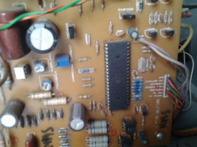
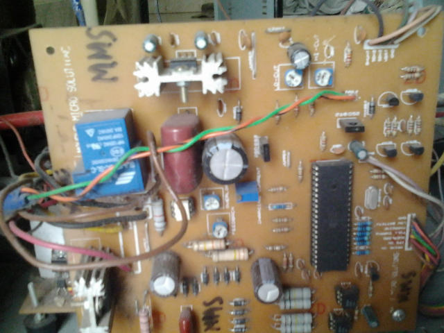
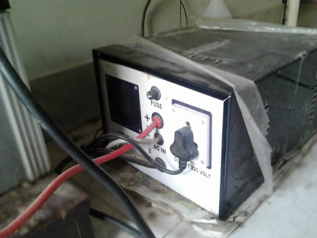
rajudp and sahu wanted to see pics of my inverter that I mentioned earlier in another post, so here it is. For the benefit of the members, I describe the circuit as:

*single microcontroller/controller (ATMEGA16/32)
*no op-amps, only chips are the micro, opto-couplers and regulator (7805)
*low-battery/overload/short-circuit protection
*thyristor controlled battery charger, using the MOSFET body diode as the AC-DC rectifier
*charger maintains the battery voltage (top) between 13.2-13.5v (adjustable) to maximize the battery life
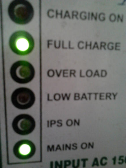
*6-LED display
*Only 93 parts in entire control circuit
*Delay between switchover to prevent inrush current

The method used here, described for those who may benefit from it:
-Initialize all ports and peripherals[ADC, Timers, Compare Modules]
-Initialize interrupts for Timer0 and compare module for
-For PWM, use Timer1 and 16-bit Phase and Frequency Correct PWM mode so the PWM runs completely on the hardware level without need for interaction to keep it running
-The AVR senses whether mains is present or not using a standard opto (4N35).
-If mains present, check battery level
-If battery level < 13.5v (this voltage is set using a pot, so can be easily adjusted), charge at the set current(set with a pot)
-If battery level > 13.5v, stop charging
-While battery > 13.2v, stop charging
-If battery voltage drops instantly start charging again
-Triac based, uses Timer0 and compare module with interrupt for phase angle control for fast charge, never overcharges battery, battery hasn't ever heated up till now and 2 year old battery still gives good backup, so charging algorithm is good for battery life
-Check mains
-If mains absent, initialize Timer and start PWM
-Check battery voltage, stop PWM and indicate on LED when battery falls below 10.8v (this is also set with a pot), response time is fast so a short circuit that produces an instant voltage drop is detected
-Check load level, check against preset level (set with pot) and if too high, shut down and indicate
-Check output voltage, adjust as required
-Check mains

*Coding is done with mikroBASIC PRO for AVR

*All voltages mentioned, eg 13.2v, 13.5v, 10.8v, Overload voltage, etc are all adjustable and set with variable resistors
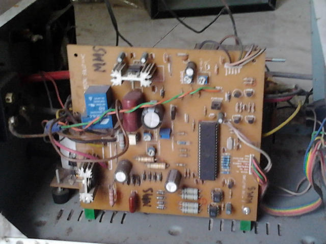
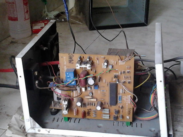
71_1291997175.jpg


65_1291997175.jpg


12_1291997175.jpg


63_1291997175.jpg


91_1291997175.jpg


85_1291997924.jpg


85_1291997924.jpg


82_1291997924.jpg


I will upload the schematic and PCB design soon.

Tahmid.
 
Last edited:

Hi all,

rajudp and sahu wanted to see pics of my inverter that I mentioned earlier in another post, so here it is. For the benefit of the members, I describe the circuit as:

*single microcontroller/controller (ATMEGA16/32)
*no op-amps, only chips are the micro, opto-couplers and regulator (7805)
*low-battery/overload/short-circuit protection
*thyristor controlled battery charger, using the MOSFET body diode as the AC-DC rectifier
*charger maintains the battery voltage (top) between 13.2-13.5v (adjustable) to maximize the battery life
*6-LED display
*Only 93 parts in entire control circuit
*Delay between switchover to prevent inrush current

The method used here, described for those who may benefit from it:
-Initialize all ports and peripherals[ADC, Timers, Compare Modules]
-Initialize interrupts for Timer0 and compare module for
-For PWM, use Timer1 and 16-bit Phase and Frequency Correct PWM mode so the PWM runs completely on the hardware level without need for interaction to keep it running
-The AVR senses whether mains is present or not using a standard opto (4N35).
-If mains present, check battery level
-If battery level < 13.5v (this voltage is set using a pot, so can be easily adjusted), charge at the set current(set with a pot)
-If battery level > 13.5v, stop charging
-While battery > 13.2v, stop charging
-If battery voltage drops instantly start charging again
-Triac based, uses Timer0 and compare module with interrupt for phase angle control for fast charge, never overcharges battery, battery hasn't ever heated up till now and 2 year old battery still gives good backup, so charging algorithm is good for battery life
-Check mains
-If mains absent, initialize Timer and start PWM
-Check battery voltage, stop PWM and indicate on LED when battery falls below 10.8v (this is also set with a pot), response time is fast so a short circuit that produces an instant voltage drop is detected
-Check load level, check against preset level (set with pot) and if too high, shut down and indicate
-Check output voltage, adjust as required
-Check mains

*Coding is done with mikroBASIC PRO for AVR

*All voltages mentioned, eg 13.2v, 13.5v, 10.8v, Overload voltage, etc are all adjustable and set with variable resistors
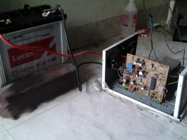
71_1291997175.jpg


65_1291997175.jpg


12_1291997175.jpg


63_1291997175.jpg


91_1291997175.jpg


85_1291997924.jpg


85_1291997924.jpg


82_1291997924.jpg


I will upload the schematic and PCB design soon.

Tahmid.


VERY NICE PROJECT ? WHAT'S PRODUCTION COST ?
i think it is a sine wave inv. i'm ok?
 
Hi,
No, this is a quasi-sine wave inverter that I made since it was more demanding than the sine at the time. I have a project with sine as well with a PIC but it's not very organized. I'll let you know the production cost in a while.
 
nice design
what is IPS on indicator?
are you driving the mosfet directly from the controller ie 5v is it a logic mosfet?
is it will support universal supply(12-48v design same board by changing some resistors values)
since there is no relay for charging section what happens if the triac is short and battery volt increases over a limit ( any indication ?)
why 5 presets are using ( output volt, battery max, charging current, overload, low battery?)

---------- Post added at 09:25 ---------- Previous post was at 09:22 ----------

sorry i have not seen the 4 transistors (mosfet driving?)
 

Hi,
IPS stands for "Intelligent Power Supply", in short the inverter. IPS on means inverter on.
No, they're power MOSFETs. The design here uses IRFZ44N x 5 on each leg for 800W. You can use other MOSFETs as well. I haven't tried though. There are 4 transistors for driving the MOSFETs, on the control board - 2xPN2222, 2xPN2907. There are 2 more transistors on the MOSFET board.
It's 12-30v with changing resistors. For upto 48v, you need to change the 7805 with an auxilary supply, that's the only change.
If battery increases while charging, then there is battery full charged indicator.
Output volt is adjusted to achieve 230V or 220V as required, that is for feedback voltage setting or output voltage setting when running in inverter mode. I set mine at 230V.
Battery max is for battery high cut voltage, to cut off charging when battery reaches a specific voltage. I set mine at around 13.5v.
Charging current is for setting the current at which battery is to be charged. I set mine for 12-15A for 70Ah battery for quick charge.
Overload is for setting the maximum load. A load (800W in this case) is applied while running in inverter mode, and the pot is adjusted slowly till at one point the inverter turns off and the LED shows overload.
Low battery is for setting battery low cut voltage. I set mine for 10.5v.
On the board, the pots are labeled "HI CUT, LO CUT, OVERLOAD, FEEDBACK, CHARGING CURRENT". The one for current is a pot that is adjustable in small units.

The 4 transistors are for MOSFET driving, the other 2 are for fan and relay.
There are 2 optocouplers, one for mains sense, the other for zero crossing detection.
I forgot to mention, this circuit requires NO AUXILIARY 9-12V TRANSFORMER.

Hope I could make it clear.
Tahmid.
 
Last edited:
what is the transformer primary volt 9-0-9 or 12-0-12 , ( output volt adjust ?)
is any separate winding for output volt sensing?
any capacitor or choke using for charging?
 
Last edited:

Hi,
The transformer I have is 12-0-12 primary, doesn't need to be accurate, since you can adjust the output voltage using the pot. What I meant is, say you wanted a 12-0-12 transformer, but you got some error, then you can just adjust the preset/pot to set output at 230v. No separate winding, feedback is done on board using diode/cap/resistor and micro. What do you mean by capacitor or choke? Charging is done using the same MOSFET board, no special capacitor or inductor, just a snubber on the board. Transformer primary is not strict. The one I used has 12-0-12 primary, secondary 0-140-280. 140 is the charger tapping, 280 is the output voltage that is adjusted.

Tahmid.
 
ok now it is clear, i was wondering hoh you regulating thye output with 240v winding , with 280v it is possible, normally here we are using a choke( now a 10uf cap in series with 140v tapping ) just not give the 230v directly to 140v winding ( in case triac problem)
 

I see, I didn't do any thing of such, but it maybe a good idea. Anyway, since I used a BTA26 I doubt it's ever gonna blow up and I'm sure my microcontroller isn't misfiring at all, so no problems yet. But doesn't hurt to be safe, you should go ahead and use it.
 
Last edited:

with firing it wont go i know, but in my place this happened with small lighting i don't know why but only the triac shorted (BT136 ), using no protection circuit the battery backep reduced fast since the water vaporizing the battery water, but your design seems good, it can be improved by adding the mosfet also to the same pcb making a single pcb design
 

Hi,
In my circuit, I've tested it numerous time and micro never misfired. Moreover, if you notice the board, you should say a hell lot of .1u ceramic caps, ie, 104pF caps. So since decoupling is so well done, I don't think there will be firing problems. A snubber may be added IF NECESSARY. I've found that the snubber isn't always necessary and gets very hot, so I omitted it, however it may be necessary in some situations so could be added there. This is also one reason I used BTA26, huge triac so that it isn't usually shorted by other factors as I know heat and firing are not issues. All in all, this seems reliable and has run over the last few months under numerous tests.
Yes, MOSFET can be added for a nice design, but I omitted it as it was more demanding to have the MOSFET board separate, in case the MOSFETs burnt. Haven't had a situation till now, but it can easily be made into one nice PCB.

Tahmid.

---------- Post added at 22:53 ---------- Previous post was at 22:49 ----------

During the testing, I've had various short-circuits at load in mains and inverter mode and nothing has happened to any part so far. So I'm confident of the design.
 

ok, i was not finding problems with your design sorry if you feel so,
the design i currently using using BT136 but it gets shorted with small lighting , i don't know why it affecting triac ( no problems with other parts ), what i thought is if a relay is added if you want use the protection you can use it or you can short the relay switch point at pcb
the pcb i am having now using tl494 to drive the mosfet( analog design)
 

Hi,
No I didn't feel anything as such, I was such talking about what happened during design. With lighting it gets shorted, I think try to add a decoupling capacitor along the power line and replace with a larger triac. There may also be misfiring problems if being driven by opamp due to noise or other factors. I haven't had a problem till now and I wanted to keep parts count to a minimum so avoided the relay as I felt it was unnecessary.

Tahmid.
 

tl494 is driving a small transformer which drives triac, there is snubber for the triac
 

I see, I didn't do any thing of such, but it maybe a good idea. Anyway, since I used a BTA26 I doubt it's ever gonna blow up and I'm sure my microcontroller isn't misfiring at all, so no problems yet. But doesn't hurt to be safe, you should go ahead and use it.


USE TWO SCR IN ANTI PARLLER DIRECTION WITH PRAPER snubber ,FOR SEFTY REASION MOSFET & CHEK I\P {I\P AC} CURRENT DURING CHARGING WITH TRIAC AND TWO SCR IN ANTI PARLLER DIRECTION . I'M SURE U CAN FOUND REASION OF
blow up UP TRIAC.
 

the triac is working fine if nothing from outside (like small lighting happens near, big we can't do anything)
 

Try with a more powerful triac in the same package. Try BT139 and see if it makes a difference.
 

USE TWO SCR IN ANTI PARLLER DIRECTION WITH PRAPER snubber ,FOR SEFTY REASION MOSFET & CHEK I\P {I\P AC} CURRENT DURING CHARGING WITH TRIAC AND TWO SCR IN ANTI PARLLER DIRECTION . I'M SURE U CAN FOUND REASION OF
blow up UP TRIAC.
I really wonder which school you studied and who is/was your english teacher. I would love to study there. I am really appreciating. Ok..anyways, as usual the forum doesnt demand upper case letters unless required and mandatory, and thus you get a warning. You need to correct it before you post anything further on this forum.
**broken link removed**
 

Tahmid can you give me transformer details
amps ?
core size ?
what about reverse protection and short circuit protection ?
does this feature include in this inverter?
 
Status
Not open for further replies.

Similar threads

Part and Inventory Search

Welcome to EDABoard.com

Sponsor

Back
Top