Continue to Site

Welcome to EDAboard.com

Welcome to our site! EDAboard.com is an international Electronics Discussion Forum focused on EDA software, circuits, schematics, books, theory, papers, asic, pld, 8051, DSP, Network, RF, Analog Design, PCB, Service Manuals... and a whole lot more! To participate you need to register. Registration is free. Click here to register now.

[SOLVED] analysis of opamp integrator circuit

Status
Not open for further replies.
AND WHY DID U ADD 10K RESISTANCE AT NON INVERTING INPUT WHY NOT SIMPLY GROUND IT

To balance the DC path on IN-
Although we neglect the input bias of the opamp, a very small current goes out from each input. They are supposed to be rather equal, so we try to let these currents see the same resistance outside the opamp. Doing this, the small offset voltages will likely be the same and this minimize the DC output offset as well.
As you see, IN- see 10K//1MEG which is almost equal to 10K, that is why I added 10K at IN+.

Obviously, in case the two input bias currents are not equal, then we will notice a DC offset at the output even if the input signal is at zero volt.
 
Last edited:

yes... a squarewave becomes a triangular one...
Now I let ic=0, which means the first triangular waveform will start from zero toward negative, between 0 and -1.
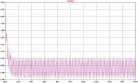
I set the "Maximum Timestep" as 10us (this slow down the simulation) and I extended, as I said, the end time to 100s ... then I contemplated the running trace... it goes slowly upwards till its has a zero average voltage.

For a reason... it liked to continue upward and swings between about +0.65V and -0.35V, hence not zero average as I was expection
yeah all this is true but whats is the reason behind it??
why it swing between 0.65 and -0.35 after 100s and swing between 0 and 1 near 1s,why there is a shift???
 

Which resistor provides the output bias?
It is Rf. In other words if we remove C1 we will get an inverted squarewave. Ideally, the inverted squarewave output should have also a zero average voltage. I think in this circuit it will be about [0.65+(-0.35)]/2 = 0.15V... I will ckeck this later. But since C1 forced the output to start from zero (then down), Rf will try driving the output to the steady state (to the offset of 0.15 in our actual circuit) by charging back C1 (10u) to its balanced state. RC time here is equal 1MEG*10u = 10sec so the circuit will need about 30us in the least to be close of its steady state...

Edited:
Please forget about removing C1, because the gain will be 1000K/10K = 100 :wink:
The opamp output will be saturated at +/- 4V for example :wink:

Of cource we can decrease the amplitude of the input from -1/+1 to -0.02/+0.02
In this case I got an output average of 144mV (as expected).
Note: to remove a capacitor, we can just give it a very small value as 1p in our circuit.

Note: You can always try to speed up the simulation by increasing the maximum timestep.

On a real circuit, one can change the value of R3 and see its effect on the output offset. I will try this now on the LTspice model.

For instance, I decreased the simulation time to 50 sec and I let the start equal to 40 sec so the average can be measured easily. Timestep=100u (I didn't try the higher values)

Added:
I find out that for this model circuit, R3=35K helped making the output offset within 2mV.
if R3<35K this offset increases (above zero) and vice versa.
I hope this answer your question why I added R3.

Added:
Let us see how a square wave becomes triangular (sawtooth means half triangular).
If the input voltage is Vin, what is the current in R2?

Equation (1)
I(R2)= (Vin-Vn)/R2
where Vn is the voltage at IN-
While the output of the opamp is not saturated we can write:

Equation (2)
Vn=Vp
where Vp is the voltage at IN+
So

Equation (3)
Vn = Vp = 0
Therefore Equation (1) becomes

Equation (4)
I(R2)= Vin/R2
This current has 3 paths after IN- but:
The path into the opamp has a relatively high resistance (impedance) so its current could be neglected.
The path into R1 (10MEG) is also very small and can be neglected.
The only path remained is of C1. We know that a constant current increases the voltage of a capacitor linearly with time because:

Equation (5)
Q = C * V
and

Equation (6)
Q = I * t
so

Equation (7)
I * t = C * V
which gives what we are looking for:

Equation ( 8 )
V = I / C * t
So while I is constant the voltage of the capacitor increases linearly with time (proportional to the charge Q = I * t)

The direction of Ic is from Vn to Vout so:

Equation (9)
I(R2) / C * t = Vn – Vout = - Vout
or after replacing I(R2) from equation (4),:

Equation (10)
Vout = - Vin * 1/ R2C * t

So the slope of Vout (time as the variable) is proportional to Vin and to the inverse of the time constant R2C.

Obviously, this simple analysis is in the time domain only and I wrote it to you because we are simulating the circuit also in the time domain.
 
Last edited:

Fareen, in order to support your understanding of the opamp integrator perhaps it helps to add three comments:
* Up to now, only the inverting integrator was discussed; however, also non-inverting types can be built with opamps.
* Up to now, all analyses from Kerim (he did a very good job!) are based on the assumption of infinite opamp open loop gain.
In reality, the real gain and phase response of the opamp will restrict the integrator operating range to frequencies far above the opamp open loop corner frequency (mostly 10...100 Hz) and far below the opamp transit frequency (app. 1...100 MHz)
It's even worse: Real and clean integration with a phase shift of 90 deg will occur at one single frequency only.
* In many integrator applications (filters, oscillators, control loops) you will see that there is no resistor in parallel to the integrating capacitor and also no discharging switch.
The reason is as follows: The integrator is used as one element in an overall negative feedback circuit (correction: loop) that provides the necessary dc stabilization.
______________________
LvW
 
Last edited:

Hi LvW,
I think the main problem in helping others remotely is that one cannot know for sure at which level the discussion can be done. If it is too high for the receiver or too low, it will be ignored automatically. If it is a bit higher or lower, new questions will come out which likely broaden the analysis to include new topics.
But on the other hand, since there will be all sort of remote helpers, the asker have more info to choose from. I try to fill the bottom level :cool:
 

...................
I try to fill the bottom level :cool:

Yes, I understand and appreciate this. In no respect, it was my intention to criticize you - in contrary, I agree with your sight.
It was my only intention to point to the fact that idealization resp. simplification of a circuit is valid only under certain conditions.
Thanks+regards
LvW
 

Sorry... it seems I gave you the impression that I had a sort of a negative feeling. My problem is that I say what comes to my mind after reading something interesting. And I forget that it may sound rather bad to some since English is my third language. For example my last sentence was meant... (though I didn't clarify it at time)... that I am getting old and my intellectual power is no more as it used to be 40 years ago (when I started to build theories to explain how radiated energy can travel in vacuum since I consider the notion of photon being just a mathematical model and doesn't represent the real mechanism).

Correction: 36 years ago :smile:
 

what would be the frequency respose of the circuit,the cut of frequency is 10hz ??
if we want to increase the cuttof frequency to 1000hz and what would be rolloff frequency and what would be the output response after cuttoff frequency,shouldnt it be zero???
 

what would be the frequency respose of the circuit,the cut of frequency is 10hz ??
if we want to increase the cuttof frequency to 1000hz and what would be rolloff frequency and what would be the output response after cuttoff frequency,shouldnt it be zero???

Fareen, I do not completely understand your question. Please, be more exact in describing the problem.
For example:
*Cut-off frequency (I suppose you mean 3-dB-frequency) for the opamp alone or for the lowpass (integrator)?
*What is the meaning of the term "roll-off frequency"?
*Why the output at any frequency should be zero?

LvW
 

by rolloff frequency i mean 3db frequency and by cuttoff mean where gain is 0db
Why the output at any frequency should be zero?
is it not true that integrator is low pass filter???
if this is true than after cuttoff frequency out put shoulndt be zero???
the circuit given above by design by kerim was having very low cutof frequency of 10u*1MEG=10Hz,so if we want to design the circuit for higher frequency e.g 1000Hz than what changes should be made
and what will be the output when input signal has frequency greater than cuttoff frequency??
 

Let us remember that the notion of cut-off frequency (Bode plot) is for sinusoidal signals.
In this case, we can write:
F (cut-off) = 1 / 2πR1C1 = 0.0159 Hz

So in our circuit "opamp_02.asc" of "LM741_test":
Vout/Vin = - R1/R2 * 1 / (1 + jwR1C1)
Vout/Vin = - 100 / (1 + jw*10)

Obviously if we let Vin be sinusoidal having 1V peak and we look to avoid opamp saturation (for this model Vout=4V if Vcc=5V), we have to start with a frequency that satisfies:
|Vout/Vin| < 4/1
( 100 / |1 + jw*10| ) < 4
|1 + jw*10| > 100 / 4
w*10 > 25 ( more accurately > 24.98 )
2*π*f > 2.5

This gives:
f (to start linear amplification) > 0.398 Hz
though F (cut-off) = 0.0159 Hz

To make the values more practical let us assume C1=10n (instead of 10u).
f (for linear operation) > 398 Hz
And F (cut-off) = 15.9 Hz (much lower)
This shows us that the cut-off frequency cannot be real for this circuit (integrator) if Vin=1, unless the amplitude of Vin is made relatively low.
For instance for Vin (peak) = 56.57 mV, f (for linear operation) = F (cut-off) = 15.9 Hz. Below this frequency the output will have saturated peaks at ±4V. Of course we can keep lowering Vin(peak) to let f (for linear) smaller than F (cut-off).

Kerim
 
Last edited:

by rolloff frequency i mean 3db frequency and by cuttoff mean where gain is 0db
is it not true that integrator is low pass filter???
if this is true than after cuttoff frequency out put shoulndt be zero???
the circuit given above by design by kerim was having very low cutof frequency of 10u*1MEG=10Hz,so if we want to design the circuit for higher frequency e.g 1000Hz than what changes should be made
and what will be the output when input signal has frequency greater than cuttoff frequency??

Fareen, in order to avoid severe misunderstandings (and not to waste time) you should try to use the standard notations and terms which are widly agreed upon.
1.) The 3-db-frequency of a lowpass is also called "cut-off" or "corner" frequency.
2.) I never have read about a "roll-off" frequency; is it your own creation?
3.) The frequency which yields 0 dB gain is often called "cross-over" frequency
4.) The output of a lowpass is zero at frequencies that (theoretically) approach infinite. Why should the output be zero at "cut-off" ? Try to understand the fundamental rules and results of circuit theory.

My advice: Use any circuit simulator and try to simulate/display the ac behaviour (transfer curve in dB as well as absolute).
Read this: https://www.edaboard.com/threads/214360/

LvW


why we get this wave form???

---------- Post added at 18:27 ---------- Previous post was at 18:02 ----------

I never have read about a "roll-off" frequency; is it your own creation?
its not my own creation this term is frequently used in our textbook written by sedria smith
 

here is the circuit
its the stupid opamp integrator im getting sick of it
 

Attachments

  • Draft1.zip
    511 bytes · Views: 83

Before I answer about your circuit, I would like you know that it is always good to insist undestanding something even in many ways, otherwise it is not science. :wink:

Edited:
Your input has a positive average voltage (have a look on its trace)... so the output should go down since the DC gain is negative... In LTpsice, Vinitial is practically the lower voltage (in your case it is better to let Vinitial -1, the opposite of Von =+1 since your duty cycle is 50%).

Edited:
I hope you know how to read the average and RMS values of a displayed waveform.
 

Attachments

  • Draft1_1.zip
    1.5 KB · Views: 59
Last edited:

u gave intial condition to the capacitor 1.6V
on what bases??? who u calculated the value???
 

I cheated. I didn't calculate it I just looked at the maximum voltage of the steady ouput.

Edited:
But it can be calculated based on equation ( 10 ) above (R2=the actual R1). Note that the result is approximated since R3 is not relatively large (just 10 times R1).
 
Last edited:

....................
its not my own creation this term is frequently used in our textbook written by sedria smith

As I am willing to learn, please, can you explain to me the meaning of "roll-off frequency" ? Thank you.
LvW

Addendum: I have searched "roll-off frequency" via google and I have found that - indeed - some people (I think mostly hobby- or audio oriented) are using this term to describe the passband edge of a filter circuit. Nevertheless, to avoid misunderstandings, one should not use both terms (roll-off and cut-off) in one sentence.
 
Last edited:

Status
Not open for further replies.

Similar threads

Part and Inventory Search

Welcome to EDABoard.com

Sponsor

Back
Top