Continue to Site

Welcome to EDAboard.com

Welcome to our site! EDAboard.com is an international Electronics Discussion Forum focused on EDA software, circuits, schematics, books, theory, papers, asic, pld, 8051, DSP, Network, RF, Analog Design, PCB, Service Manuals... and a whole lot more! To participate you need to register. Registration is free. Click here to register now.

[SOLVED] analysis of opamp integrator circuit

Status
Not open for further replies.

fareen

Full Member level 3
Full Member level 3
Joined
Oct 31, 2010
Messages
154
Helped
4
Reputation
8
Reaction score
4
Trophy points
1,298
Visit site
Activity points
2,193
hello
im attaching my ltspice circuit
i have few questions.
first whats the function of resistor 100k?why output decreases to nano volts if its value is increased???
in the output wave from through transient analysis why the gap between the ramp is small although output is 50% on and off???
the maxium output is -10V,is this becus of gain factor (-100k/10k)???
if so then we can say that capacitor have on effect on gain except for frequency???
i read that gain is (Rf/R)/[1+(1/sCRf)]???View attachment opamp.zip
and why output decrease to 0V from -10 V
 

Your circuit isn't working as an integrator for the presented input waveform. You even don't notice an effect of the capacitor in the output waveform, because the capcitance is too low. It's just a G=-10 amplifier.

To demonstrate integrator behaviour, you should find out a more suitable dimensioning and use a simple input waveform, e.g. a square pulse.
first whats the function of resistor 100k?why output decreases to nano volts if its value is increased???
A real integrator needs a means to reset it. A resistor in parallel to the capacitor is one possible option. If you took the circuit from literature, you should also review the respective explanations about reasonable part values. The output won't however decrease to nanovolt, if the resistor value is increased. Maybe, you confused mohm with megohm? Consult a SPICE respectively LTSpice manual for the correct syntax.
 

here i have attach the literature from where i took the circuit
its Mohm not mohm
and what should i do to make this circuit to make an integrator??
according to this article it should act as a integrator
 

Attachments

  • opamp.zip
    647.4 KB · Views: 158

Hi FvM,

It seems you were able to download the LTspice circuit.
On my screen I cannot find any link for it.
Should I look elsewhere?
Thank you.

Kerim

Edited:
Now I get it :wink:
Oh... it is just a reference "opamp.zip"... not the circuit
So I still miss the original one.
OK case is closed, "opamp.zip" has both.
 
Last edited:

its Mohm not mohm
That's why I suggested to learn about SPICE syntax. SPICE isn't case sensitive, you need to write meg or MEG instead of M.
according to this article it should act as a integrator
It surely can, but not for your input waveform.

P.S.: Why don't you simply reproduce the input waveform used in the literature? It's a rectangular pulse, as I suggested before.

I also see a detailed explanation about the purpose of the parallel resistor.
 
Last edited:

yeah i got that right i forget,silly me.
The rf resistor is providing the dc gain and stoping the infinte loop gain when input is zero,right???
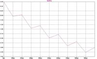
now i got this kind of wave from i made sum changes in the voltage source

and i didnt get a word from the article, need sum explanation or time to go through the article again.:(
 

Let us see how we can get the main idea of this integrator in a simple way.

First, we assume that the opamp is supplied by Vcc+ and Vcc- . To be sure that we simulate the circuit in our mind, it is better to use the symbol opamp2 which has the V+ and V- supply pins. I am not note which opamp model is available to you. We need to add two simple voltage sources for Vcc+ and Vcc- and give them the values +5V and -5V for example.
 
Last edited:

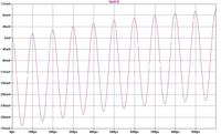
and if providing sine input to the integrator ,the output is cosine but its like this.why??


---------- Post added 30-05-11 at 00:10 ---------- Previous post was 29-05-11 at 23:59 ----------

using op amp2 is giving error even if i add a path to the library
i used universal opamp but gives the same output no difference
do u think the output shown are correct???
 
Last edited:

Yes you are right because opamp2 expects a model (with 5 pins) to be added (as a file for example) in the same directory of the *.asc file.
To be honest, I did simulate a lot of complex circuits (both analogue and digital) on LTspice. This is my first time I try to simulate the well known integrator using opamp. The first result I got (using LM324 and +/- 5V as dual supply) is like yours of post #8 :smile:

The reason is a pulse 0/1 is AC + DC :wink:

Now -1 +1 make the integrator happy :D
 

Attachments

  • opamp_.zip
    2.6 KB · Views: 143
Last edited:

this mean that its the correct output wave form
yepppi:)
but i still doesnot know the reason for the strange 2nd output.
and do u have any idea where lm741 exist in ltspice i couldt find it
i have to simulate this circuit using lm741 in my lab
 

KerimF
i didnt have the library file for opamp so circuit is not runing:(
found it :)
 
Last edited:

I hope you got the file LM741_mod.txt (it is in LM741_test.zip) , if you did just put a copy of it in your working directory.
Then on your schematic add .inc LM741_mod.txt
OK?

For instance you can rename LM741_mod.txt as you like, perhaps LM741.lib (since you like the extension lib :wink: ) but in this case the include command should be:
.inc LM741.lib on your schematic.
 

in ur circuit for the viltage source u set the Vintial to -1V why????
doing this give sawtooth waveform
 

No, just to let the input squarewave alternates between -1 and +1 so that its average voltage is zero.

Did you noticed, ic=0.5V (the initial voltage of C1)? I did it to get a symetrical output at the start of the simulution.... but I face now another problem :-(
By curiosity, I extended the simulation time to 100 sec... and what I get?...
I think it is about a setting on LTspice. Perhaps the "Maximum Timestep" should be made small and not left as default.
 
Last edited:

so u say sawtooth output should be observed at Vo of integrator opamp when pulse input is provided
 

yes... a squarewave becomes a triangular one...
Now I let ic=0, which means the first triangular waveform will start from zero toward negative, between 0 and -1.
I set the "Maximum Timestep" as 10us (this slow down the simulation) and I extended, as I said, the end time to 100s ... then I contemplated the running trace... it goes slowly upwards till it has a zero average voltage.

For a reason... it liked to continue upward and swings between about +0.65V and -0.35V, hence not zero average as I was expecting :???:
 
Last edited:

By curiosity, I extended the simulation time to 100 sec... and what I get?..
I DID THAT ONE BEFORE :p
GIVING IC=0.5 JUST SHIFT THE GRAPH UPWARD BY 0.5v DOES NOT CHANGE ANY THING ELSE
AND WHY DID U ADD 10K RESISTANCE AT NON INVERTING INPUT WHY NOT SIMPLY GROUND IT
 

Status
Not open for further replies.

Similar threads

Part and Inventory Search

Welcome to EDABoard.com

Sponsor

Back
Top