Continue to Site

Welcome to EDAboard.com

Welcome to our site! EDAboard.com is an international Electronics Discussion Forum focused on EDA software, circuits, schematics, books, theory, papers, asic, pld, 8051, DSP, Network, RF, Analog Design, PCB, Service Manuals... and a whole lot more! To participate you need to register. Registration is free. Click here to register now.

analysis for 100w amplifier ciruit

Status
Not open for further replies.
The differential pair has a high emitter resistance and drives the low input resistance of the TIP41 so its gain is low or it has loss.

The TIP41 has the most gain of maybe 120.

The darlingtons are emitter-followers with no gain.

Therefore the total open-loop gain is low.
 

should I substitute TIP41 with a darlington transistor or another transistor?

Added after 2 hours 43 minutes:

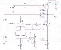
anyway i modified the circuit again
now it gives me around 0.086% at 1mv
here is the sch
is there any improvement that can be made?
 

Replace R13 with a current source that has a very high impedance for a very high gain from the TIP41 transistor.

Remove R2.

Replace the three huge diodes with two normal 1N4148 diodes.
 

    mr_byte31

    Points: 2
    Helpful Answer Positive Rating
for the diodes I couldn't find 1N4148 in orcad so i used any diode
Ok i will remove R2 and see the effect
i tried simple current mirror using 2N2222 but it gives a very low current with a very bad performance (current = in nA)

Added after 7 minutes:

should i use current source like that
**broken link removed**
 

This amplifier is very similar to yours. **broken link removed**
It produces 60W into 8 ohms or 100W into 4 ohms. Its distortion is only 0.04% at 50W into 8 ohms.

1) It uses a current source at the emitters of the differential pair of input transistors.
2) It uses an adjustable Vbe multiplier transistor instead of diodes to bias the output transistors.
3) It uses a bootstrap capacitor C5 to increase the output power and increase the gain of Q4.
4) It has frequency/phase compensation capacitors.
 

I have a little question
in the diff amplifier why didn't he use a current mirror as a load?

Added after 1 hours 12 minutes:

another question plz :)
could I use TIP41 and TIP42 for the last stage??
TIP41/42 can supply till 6A
I would use 3A or less to have 72W in 8 Ohm speaker
is that correct?
 

If the diff amp uses a current mirror as its load then the amp will have a higher open-loop gain which would be better because then its negative feedback will be more and its distortion would be less.
But it would be more complicated and cost more.

72W into 8 ohms is a signal of 24V RMS which is 34V peak. Then you need a plus and minus 36V to 38V power supply.

34V/8 ohms is a peak current of 4.25A.
The TIP41 and TIP42 have a minimum current gain of only about 10 at such a high current.
They might melt with such a high power dissipation.
 

I am sorry but I couldnot understand
If the collector current is 4.25A this is still Ok because the transistor can drive till 6A.!!!
 

The datasheets for the TIP41 and TIP42 shows that they can survive 6A, they don't show their extremely low performance at such a high current.

Never ever use a transistor at its max rating.
 

but there is a 2A difference !!?
Ok i may use 2SC5200/A1943 or 2SA1216/2SC2922.?
whats ur idea?
 

A 4 ohm load uses much more current than an 8 ohm load.

I have never used Japanese, Korean nor Chinese transistors and I probably never will. So I didn't look at their datasheets.
 

now I am finishing the PCB but I think I need a preamplifier for Mic
I am thinking about a popular IC that can amplify the mic signal and add some effects(bass, treble, echo, repeat)
do you have any experience about that?
 

Status
Not open for further replies.

Similar threads

Part and Inventory Search

Welcome to EDABoard.com

Sponsor

Back
Top