Continue to Site

Welcome to EDAboard.com

Welcome to our site! EDAboard.com is an international Electronics Discussion Forum focused on EDA software, circuits, schematics, books, theory, papers, asic, pld, 8051, DSP, Network, RF, Analog Design, PCB, Service Manuals... and a whole lot more! To participate you need to register. Registration is free. Click here to register now.

[SOLVED] Analog Circuit Design for Switching circuit

Status
Not open for further replies.

jai patel

Newbie level 3
Newbie level 3
Joined
Mar 18, 2014
Messages
3
Helped
0
Reputation
0
Reaction score
0
Trophy points
1
Activity points
26
Hello Everyone,

I am using PIC16F887, MOSFET IRF540n and 24V power supply and using this I have design a switching circuit as below.
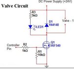
Capture.JPG

here I am using 24V power supply and solenoid valve which need 24V to start and 5kohm of resistor in series with LED to show that switch is ON and OFF. and it works fine.

Now if I want to design circuit for 12V valve then how I calculate resistor value in series with LED.

and if I want to use only single circuit for either 12V or 24V power supply then can I?
 

Hi jai patel,
The selection of series resistor depends on the voltage value and current rating of the selected LED.
The series resistor serves as current limiter for LED.

For most of the LEDs 2mA to 3mA is sufficient for producing luminous intensity.
In the +24V case, the current for LED is 4.8 mA.(24/5K)
If this circuit (+24V) works fine, then for +12V circuit by maintaining same current of 4.8 mA, the required resistor value should be around 2.5K Ohms.

Your second question is, you are meaning to say whether you change voltage to +12V or +24V, you want the single resistor.
If this is the case you have to know about minimum and maximum current rating of LED.

If you part no of LED, i can help u.

Regards,
Shunmuga Sundaram
 
A logic level MOSFET would be more suitable in this circuit.

However, to answer your question, the value for R3 is calculated as (supply voltage - LED forward voltage - drop across MOSFET) / LED current. If I assume you are using a normal indicator LED with a Vf of around 1.6V and the MOSFET is fully conducting, the LED is passing (24 - 1.6 - 0)/5000 = 4.48mA. If you drop the supply to 12V, it will only pass ~2mA which will probably make it rather dim. To keep the same current at 12V supply, the value should be 2.08K (use 1.8K or 2.2K standard values).

There is no simple way to make the brightness the same at both supply voltages but if you use a resistor of say 2.7K it should still be bright enough at 12V but not too bright at 24V.

Brian.
 
Instead of a resistor in series with the LED, use a two terminal, current source in series with the LED. This circuit will make the LED brightness independent of the supply voltage. Search "current source". There are many solutions such as a ICs for this function or simple circuits with depletion mode MOSFETs, etc.
 

If your load current is < 2 A, I would recommend to use the PVG 612, the optocoupler with a high power output, 60 V, 2A. It is driven by TTL, 5 mA input through a 1..3 kOhm resistor, and also requires the diode across an inductive load. For ON indication, you can use a LED in series with the input resistor. I tested such device for temperature response, under a full 2A load it died at >120 deg.C. No heat-sink needed.
 

the most simple way to use a resistor that allows the LED to light sufficiently - say 3 to 4mA at 12V, but not allow current to go over the max at 24V

beyond that a 2 transistor current limiting circuit for the LED will work
 

Status
Not open for further replies.

Similar threads

Part and Inventory Search

Welcome to EDABoard.com

Sponsor

Back
Top