AMAN SAXENA_E_S
Newbie

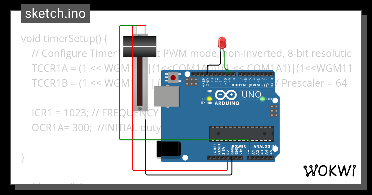
ADC WORKING Copy - Wokwi ESP32, STM32, Arduino Simulator
Run IoT and embedded projects in your browser: ESP32, STM32, Arduino, Pi Pico, and more. No installation required!
 wokwi.com
[Moderator action]
- Paste here the code took from the external link.
Code C - [expand]
Last edited by a moderator:
