Continue to Site

Welcome to EDAboard.com

Welcome to our site! EDAboard.com is an international Electronics Discussion Forum focused on EDA software, circuits, schematics, books, theory, papers, asic, pld, 8051, DSP, Network, RF, Analog Design, PCB, Service Manuals... and a whole lot more! To participate you need to register. Registration is free. Click here to register now.

A varying-frequency control Flyback rectifier for constant current LED driving in Boundary-Conduction Mode

Patrick_66

Member level 3
Member level 3
Joined
Nov 18, 2023
Messages
62
Helped
0
Reputation
0
Reaction score
0
Trophy points
6
Activity points
427
Greetings everyone, there are a few questions that I'm hoping that you guys can help me to solve. What does it actually mean from the title that I had written above? Is it varying the input voltage while the output current remain the same at all times ? What is actually the use of a feedback controller is it to maintain a constant current by varying the frequency of the switch or is the controller used to ensure that the whole system is always running in BCM mode? Sorry for my ignorance guys. I hope that someone can help me. Thank you.
 
What power you want?
0.5*L*I^2*f give you the values.
You pick a suitable frequency......or get the excel open and play eith it to see.

Do it postulatively....its good excel for that....stuff in a value, see how it comes out, then change to suit....you can get a really small worksheet liek that which is good.

Get an excel worksheet open and start playing.
Otherwise give me your spec and i do for you in minutes and send back to you here...
--- Updated ---

What power you want?
0.5*L*I^2*f give you the values.
You pick a suitable frequency......or get the excel open and play eith it to see.

Do it postulatively....its good excel for that....stuff in a value, see how it comes out, then change to suit....you can get a really small worksheet liek that which is good.

Get an excel worksheet open and start playing.
Otherwise give me your spec and i do for you in minutes and send back to you here...

The output power is around 10 to 24 W. Can you share to me your excel file for me to play around with the figures. Thank you for your help.
 
Hi,
OK i give you here 30V and 21W. It is BCM as you wish.
You did not spec the vin etc so i made that for you.
There is LTspcie confirmatory sim aswell
(Any hints on why this forum is so slow on my laptop when i am on public wifi, much appreciated, maybe i have an internet setting wrong?)
--- Updated ---

if you give me full spec, i change that excel for you in minutes to match the spec, and send it back here for you.
I even do transformer aswell if you want.
 

Attachments

  • BCM Flybak.zip
    7.2 KB · Views: 103
  • Flyback _BCM _LT3799 _Forum.zip
    2.3 KB · Views: 100
Last edited:
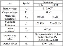
Here is my spec, if possible can you help me to change it?
May I ask what equations you use to get the results in your Excel file?
How did you get all the other values that I circled based on the Figure below?
 

Attachments

  • Spec.png
    Spec.png
    86.2 KB · Views: 85
  • ask.png
    ask.png
    85.1 KB · Views: 88
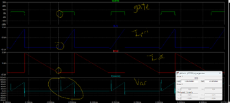
Is this BCM mode or DCM mode because the Isec drop to 0A before the MOSFET switches 'ON' ?
--- Updated ---

Hi,
OK i give you here 30V and 21W. It is BCM as you wish.
You did not spec the vin etc so i made that for you.
There is LTspcie confirmatory sim aswell
(Any hints on why this forum is so slow on my laptop when i am on public wifi, much appreciated, maybe i have an internet setting wrong?)
--- Updated ---

if you give me full spec, i change that excel for you in minutes to match the spec, and send it back here for you.
I even do transformer aswell if you want.
May i ask the simulation that you proposed is it a constant current LED driver or constant voltage LED driver ?
 

Attachments

  • ask2.png
    ask2.png
    86 KB · Views: 79
Last edited:
Hi,
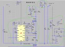
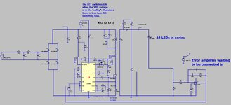
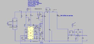
The attached is bcm led driver in LTspice doing 24 leds at 350mA from 110VAC input. It has PFC.
Its running open loop, so if you wish it regulated, youll need to connect in the error amplifier....but PFC loops take ages to simulate so not sure if you wish to do this.

Its 50khz at the mains peak...obviously more at the sides
 

Attachments

  • BCM PFC led driver.jpg
    BCM PFC led driver.jpg
    188.7 KB · Views: 85
  • Flyback _BCM _LT3799 _PFC_Forum_231202.zip
    2.8 KB · Views: 78
Hi,
The attached is bcm led driver in LTspice doing 24 leds at 350mA from 110VAC input. It has PFC.
Its running open loop, so if you wish it regulated, youll need to connect in the error amplifier....but PFC loops take ages to simulate so not sure if you wish to do this.

Its 50khz at the mains peak...obviously more at the sides
Hello Sir, may I ask if this is a constant voltage LED driver because when I try to increase the number of LEDs the system does not manage to regulate the output current only the output voltage is regulated. Can this IC be used to regulate constant output current because I wanted to learn how to regulate the output current of the load where the output current will still remain at 350 mA even though I increased the number of LEDs. One more question, the equation to select the inductor and capacitor values is based on the IC that you use in your system? Thank you for your help so far, I really appreciate it. Moreover, thank you for responding even though I keep asking so many questions. Hope to hear from you soon.
 
Hi,
Its neither constant voltage or constant current regulated....as you can see, the feedback voltage is a fixed dc voltage...this was done because i didnt have the time to connect in the current error amplifier which is shown there....because pfc feedback loops take ages to simulate....but yes...if you connect in the shown current error amplifier then it will be output current regulated.

You can see in the sim there is an unconnected current error amplifier, waiting for someone to connect it up.....then it will be constant current regulated.

An error amplifier is usually an opamp "integrator", which is what you can see on the sim.

Do you know the rule that opamps with negative feedback tendd to end up with both their inputs at the same voltage?.....thats kind of whats involved in an error amplifier.

Later, when i have time, i will remove the PFC aspect, and just make it current regulated.....then it will run quicker...but i thought you need pfc as your power is 24w and its lighting?

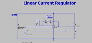
But first, i believe you may benefit from some "error amplifier practice"...so here attached is an ltspice current error amplifier for you to practice on......exactly the same opamp cct is used for smps too, so it is good practice.........play around with it if you wish
 

Attachments

  • Linear current regulator1.jpg
    Linear current regulator1.jpg
    132.4 KB · Views: 78
  • Linear current regulator1.zip
    772 bytes · Views: 75
Hi,
Its neither constant voltage or constant current regulated....as you can see, the feedback voltage is a fixed dc voltage...this was done because i didnt have the time to connect in the current error amplifier which is shown there....because pfc feedback loops take ages to simulate....but yes...if you connect in the shown current error amplifier then it will be output current regulated.

You can see in the sim there is an unconnected current error amplifier, waiting for someone to connect it up.....then it will be constant current regulated.

An error amplifier is usually an opamp "integrator", which is what you can see on the sim.

Do you know the rule that opamps with negative feedback tendd to end up with both their inputs at the same voltage?.....thats kind of whats involved in an error amplifier.

Later, when i have time, i will remove the PFC aspect, and just make it current regulated.....then it will run quicker...but i thought you need pfc as your power is 24w and its lighting?
Hello Sir, now I will go and straightaway refresh my memory on the working principle of an opamp. Thank you very much for taking the trouble to help me simulate it, very appreciate your help. Ohh, for now you can remove the PFC aspect because now I just wanted to focus on how to build a constant current LED driver in BCM mode. Thank you for your response and very very thank you for helping me to simulate the system.
 
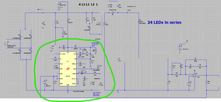
OK here is constant current offline led driver to your spec...in LTspice....no PFC....it is reg'd to 333mA...you can change the reference to the error amplifier to get it to 350mA if you want.
 

Attachments

  • Flyback _BCM _LT3799 _NoPFC_Forum_231202.zip
    2.8 KB · Views: 70
  • BCM PFC led driver no pfc.jpg
    BCM PFC led driver no pfc.jpg
    206.8 KB · Views: 66
Wow, thank you so much. If it is okay with you, can you teach me how you calculate the inductance value of the coupled inductor? If I change the values of the resistance, and capacitance near the IC will it affect the whole system? Thank you for your time.
 

Attachments

  • Diagram.png
    Diagram.png
    83.5 KB · Views: 72
all the equns you need are in post #14...and you need read LT3799 datasheet.
I actually forgot to put a constant voltage into the vin_sense pin but it still works pretty well.
It really needs around 1v fixed into that....for non pfc apps
 
all the equns you need are in post #14...and you need read LT3799 datasheet.
I actually forgot to put a constant voltage into the vin_sense pin but it still works pretty well.
It really needs around 1v fixed into that....for non pfc apps

Hello Sir, I will go and have a look at the datasheet and thank you for taking your time to slowly teach me even though i have no knowledge in this field. Hope that you are doing well and have pleasant day ahead of you.
 
OK thanks, in order to help you it is needed to ask you to complete the following sentence...

"If a voltage of 1Volt is held across an ideal inductor of 1 Henry, then the rate of change of current in that inductor is .........."

If you cannot completing this sentence, then you need to looking into this before any further helps can be given.
It is Lenz's Law.
Hello, Sir. It is me again. After seeing the datasheet I have a few unsolved questions that I need your help with. I did not manage to find the inductance value for the transformer. Maybe the datasheet inside got mentioned indirectly but I'm unable to catch on. Sir, can you help me with that? Based on the pdf file below I have used some of the equations to obtain the value for duty cycle, Rsense and Iout (max) but for the Rsense I did not manage to get the same value as your design based on the input voltage of 110 Vac, output voltage of 80 Vdc and I out = 333mA as you mention before. Furthermore, how did you get the resistance and capacitance value that I had circled based on the pdf file below because the datasheet did not mention how to calculate it. Other than that, if the external error amplifier connects to the IC at the primary side does this system still have isolation properties? The external error amplifier will replace the function of COMP in the IC if I'm not mistaken. Based on the simulation that you showed me, if not mistaken the system did not include dimming feature, PFC, Open and short LED indication right? Sorry for asking so many questions. Hope that you can help me. Thank you for your time and effort to teach a person like me. Hope to hear from you soon.
--- Updated ---

Hello, Sir. It is me again. After seeing the datasheet I have a few unsolved questions that I need your help with. I did not manage to find the inductance value for the transformer. Maybe the datasheet inside got mentioned indirectly but I'm unable to catch on. Sir, can you help me with that? Based on the pdf file below I have used some of the equations to obtain the value for duty cycle, Rsense and Iout (max) but for the Rsense I did not manage to get the same value as your design based on the input voltage of 110 Vac, output voltage of 80 Vdc and I out = 333mA as you mention before. Furthermore, how did you get the resistance and capacitance value that I had circled based on the pdf file below because the datasheet did not mention how to calculate it. Other than that, if the external error amplifier connects to the IC at the primary side does this system still have isolation properties? The external error amplifier will replace the function of COMP in the IC if I'm not mistaken. Based on the simulation that you showed me, if not mistaken the system did not include dimming feature, PFC, Open and short LED indication right? Sorry for asking so many questions. Hope that you can help me. Thank you for your time and effort to teach a person like me. Hope to hear from you soon.
 

Attachments

  • LT3799 IC_231207_214513.pdf
    3.2 MB · Views: 72
  • Important _231207_225826.pdf
    3.3 MB · Views: 101
Last edited:
OK thanks, in order to help you it is needed to ask you to complete the following sentence...

"If a voltage of 1Volt is held across an ideal inductor of 1 Henry, then the rate of change of current in that inductor is .........."

If you cannot completing this sentence, then you need to looking into this before any further helps can be given.
It is Lenz's Law.

Hope to hear from you soon Sir. Thank you for your time Sir.
 

LaTeX Commands Quick-Menu:

Part and Inventory Search

Welcome to EDABoard.com

Sponsor

Back
Top