crutschow
Advanced Member level 6

- Joined
- Feb 22, 2012
- Messages
- 4,519
- Helped
- 1,003
- Reputation
- 2,004
- Reaction score
- 1,146
- Trophy points
- 1,393
- Location
- Colorado USA Zulu -7
- Activity points
- 25,711
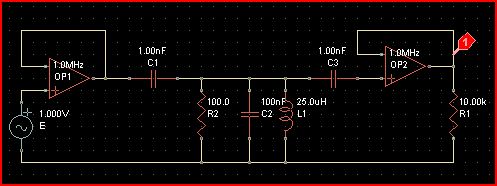
What do you mean, they are 180° opposite each other? Do you mean the obvious -- that when the current is coming out of the inductor, it is going into the capacitor terminal connected to the same node?The currents in the L branch and the C branch of a parallel circuit are 180° opposite each other no matter what the voltage frequency is.
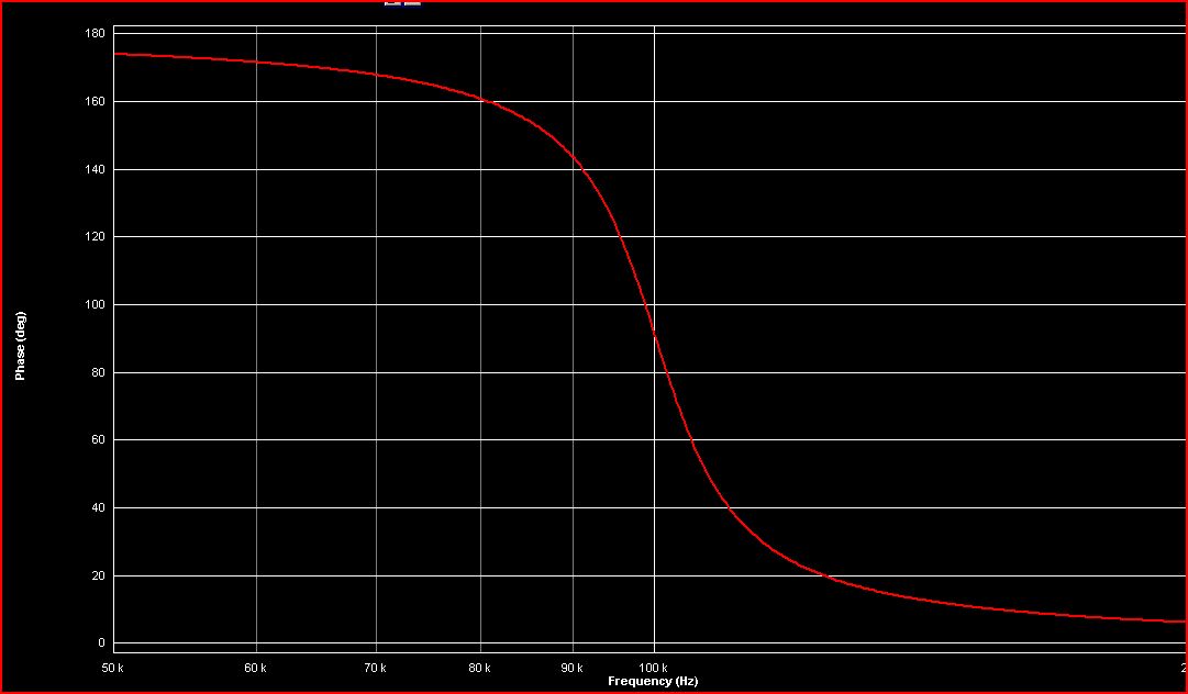
How is that relevant to achieving a 90° phase shift? :?:


")