dabby21
Advanced Member level 4

- Joined
- Aug 8, 2011
- Messages
- 114
- Helped
- 0
- Reputation
- 0
- Reaction score
- 0
- Trophy points
- 1,296
- Location
- Philippines
- Activity points
- 2,232
Nice to know that you managed to get an LM3914. I had already designed a circuit using two LM339 comparator ICs, but the LM3914 design is more compact. Don't worry about the N suffix. Popular ICs are often made in many different packages, temperature range, etc. The N simply denotes that particular type of plastic package. Such suffixes are often omitted in schematics and discussions.
The battery is connected to the UPS as in the schematic. The monitoring circuit is connected to the battery as in the schematic. That is, the battery is connected to both the UPS and the monitor circuit at the same time. The "+12V BATT" terminal at the bottom of the schematic goes to the battery and serves as both the power supply and the voltage sensing point. This is shown in the diagram below which shows parts of the UPS and the monitor circuits -
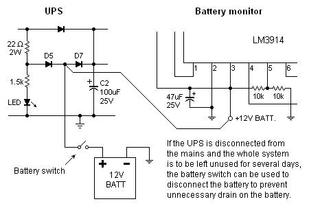
There is no 2.2 ohm resistor in the UPS circuit. It's 22 ohms. Yes, it's OK to use a 5W resistor, and wirewound is fine too. All other resistors are 1/4W. It's OK to use higher wattages, the only difference being that they will be bigger and more expensive.
If you're still not clear about something, just ask again.
Sirs,
The UPS circuit is successful, thank you so much sirs!
I did the battery monitoring sirs, but none of the LEDs are on. when i connected to the battery directly, same goes with the circuit just like on the picture above. I did test some readings on the battery monitoring circuit but theres no reading at all on the LED copper, yet there is 12 V input on the circuit.
Here's our schematic sirs.
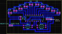
please sirs, have a look on it

