Continue to Site

Welcome to EDAboard.com

Welcome to our site! EDAboard.com is an international Electronics Discussion Forum focused on EDA software, circuits, schematics, books, theory, papers, asic, pld, 8051, DSP, Network, RF, Analog Design, PCB, Service Manuals... and a whole lot more! To participate you need to register. Registration is free. Click here to register now.

RF Receiver Interface to AT89c52

Status
Not open for further replies.

Help

Advanced Member level 2
Joined
Feb 15, 2005
Messages
617
Helped
7
Reputation
14
Reaction score
3
Trophy points
1,298
Activity points
7,065
rf reciver

Hi,

Can we direct interfacing the receiver output to uC? withou connet any decoder IC.

I have one RF transmitter and receiver car remote control. I don't have oscilloscope to measure the incoming receiver. So, i try to write the decode coding and RS232 coding in my uC for simulate. I assumed the receiver generate 16bits output signal, then i will decoded it to 8bits then display the result via RS232.

But the problem is i can't get very actual result and it generate all differents signal.
May i know the receiver output signal will the signal be at a constant bit rate ? and
will the data to be received start will a known start pattern ?

What can i do for my next step?

Thank You.
 

manchester encoding +code

Hi,

Ya, you are right. something like yours. but my only got 4 pin which is Out, Ant, Vcc and Gnd.

So what are the following step i need to do?

Thank You.
 

at89s52 int0 button

At transmitter end connect one micro's TX pin to Data In, and at the receiver end connect receiver Data Out to another microcontroller RX pin, set baud rate to 300 (max 1200) and try to send a byte ..

Regards,
IanP
 

rc cars using at89c52

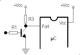
1. Make sure the OUT is a TTL level signal, if you don't sure use conection as diagram below
2. Connect the OUT pin to uC and measure the '0' and '1' duration on certain periode (ie 1 second) while the transmitter transmit data
3. The recorded data can be use to recognize the signal

99_1169091402.gif
 

at89c52 remote control car

Hi,

I don't know where is the transmitter output because i bought the Car Remote Control which is made-ready one. The pcb alot of SMD IC and with 2 big button (i think it builded in with encoded). Latter i will post my transceiver photo. I try to find the output 1st.


IanP said:
At transmitter end connect one micro's TX pin to Data In, and at the receiver end connect receiver Data Out to another microcontroller RX pin, set baud rate to 300 (max 1200) and try to send a byte ..

"We try to send a byte" means we press the transmitter button then it will send a byte. My microcrontroller will received the data from receiver then how/where can i know the simulate the result through LED display, LCD or PC-Interface but uC only have one RS232. The data will be very fast.

Thank You.

Added after 16 minutes:

Hi,

budhy said:
Make sure the OUT is a TTL level signal, if you don't sure use conection.
I got but a 7404 between the receiver and uC port.

budhy said:
Connect the OUT pin to uC and measure the '0' and '1' duration on certain periode (ie 1 second) while the transmitter transmit data
I try this before. I connect the receiver out to T2EX and set to counter-mode to count the transition every 0.5Sec then show it on LCD. It quite stable.
Is it what you mean?

Thank You.
 

th0 tl0 10000

I try this before. I connect the receiver out to T2EX and set to counter-mode to count the transition every 0.5Sec then show it on LCD. It quite stable.
Is it what you mean?
No, not like that.
The signal is combination of '0' & '1' stream with difference pulse width, so you have to measure the each pulse. Because we don't know how length the stream is, so measure it at certain of periode (ie 0,5 second)
 

    Help

    Points: 2
    Helpful Answer Positive Rating
interrupt in at89c52

Do you mean we have to measure the '0' time and the '1' time then store each in the Buffer itself. After 0.5Sec we check the time '0' buffer and '1' buffer was taken. Am i rite?

Thank You.
 

at89c52 rf

Yes!
At a periode of 0,5 second, we'll get many set of signal stream, then we have to select a complete set of steam visually.
 

    Help

    Points: 2
    Helpful Answer Positive Rating
rf receiver dataout

Hi,

budhy said:
Yes!
At a periode of 0,5 second, we'll get many set of signal stream, then we have to select a complete set of steam visually.

I already done the testing that we discuss early.
1) Wrote a Manchester Encoding code.

2) Set Timer0 T0 in mode 1, 16-bit Timer

3) While enter the INT0 Interrupt Service Routine (falling edge) - store TL0 value in Buffer1 then reset TL0 run the TR0 again for raising edge time.

4) While enter the INT1 Interrupt Service Routine (raising edge) - store TL0 value in Buffer2 then reselt TL0, run the TR0 again for falling edge time.

5) If the incoming signal is falling edge 2 times, the Buffer1 store 2 time and the Buffer2 store "0" (entry time). Raising 2 times, Buffer2 store 2times Buffer1 store "0".

I already probe out the graph. There are two type of graphs "transmitter without transmit data" and "transmitter transmit data" but i can't make any conclusion. Please can you check it for me?

Thank You.
 

Could you tell me your description is for a Manchester Encoding of for RF control signal capturing?

Please can you check it for me?
Can you send me the capturing data?
 

    Help

    Points: 2
    Helpful Answer Positive Rating
whi u don't use decoder
i think it will be more easy, i make remote conreol for my car , and i buy a china RF moduls for central locking door (car) , after that i remove the original MCU and connect to 8051 with buffer and after that just reading the buttons :))

regards SYRAX
 

budhy said:
Could you tell me your description is for a Manchester Encoding of for RF control signal capturing?
The code is same as yous but i only add Measure Time and Record for the recording data.

That is another post that you helped me before. This is in assamble language:
Code:
State   bit   0 
; 
    ORG   0x0000 
    AJMP  Start 
; 
;*** INT0 Interrupt Service Routine 
; 
    ORG   0x0003 
    SETB  State         ; it is '1' 
    SETB  EXF2          ; transition occured 
    RETI 
; 
;*** INT1 Interrupt Service Routine 
; 
    ORG   0x0013 
    CLR   State         ; it is '0' 
    SETB  EXF2          ; transition occured 
    RETI 
; 
;*** Transition detected (Timer 2 Interrupt Service Routine) 
; 
    ORG   0x0023 
;   do some thing here 
    CLR   EXF2 
    RETI 
; 
;*** Main Program 
; 
Start: 
    SETB  EX0 
    SETB  EX1 
    SETB  ET2 
    SETB  EA 
Here: 
    SJMP  Here

And this is my C language:
Code:
void Interrupt_INT0_Routine(void) interrupt INTERRUPT_EXTERNAL_0  
   {
//_______________ Measure Time and Record ________________
	TR0=0;
	Buf0[c0++]=TL0;

	if(pulse_state)
	{
		Buf1[c1++]=0;
	}
	else
		pulse_state=1;

    TH0 = 0;  
    TL0 = 0; 
	TF0 = 0;          // clear overflow flag
	TR0 = 1;          // start timer 0
//_____________________________________________________

	edge = RISING; // 1
	EXF2 = 1;
   }   

void Interrupt_INT1_Routine(void) interrupt INTERRUPT_EXTERNAL_1 
   {
//_______________ Measure Time and Record ________________
	TR0=0;
	Buf1[c1++]=TL0;

	if(!pulse_state)
	{
		Buf0[c0++]=0;
	}
	else
		pulse_state=0;

    TH0 = 0;  
    TL0 = 0; 
	TF0 = 0;          // clear overflow flag
	TR0 = 1;          // start timer 0
//_____________________________________________________


	edge = FALLING; // 0
	EXF2 = 1;
   }   

void Interrupt_T2EX_Routine(void) interrupt INTERRUPT_Timer_2_Overflow 
   {

	EXF2 = 0; // Clear the flag
 
//_______________ Measure Time and Record ________________
	if(c0+c1 >= (Bf0+Bf1))
	{
		EX0 = 0; // ***ON External0 interrupt
		EX1 = 0; // ***ON External0 interrupt
	}
//_____________________________________________________
   }
Initail Interrupt Routine:
Code:
void Interrupt_Routine_Init(void) 
   {
    WRITE_TMOD_T0(1); // Set required T0 in mode 1, 16-bit Timer 

   ET0 = 0;  // No interupts
   ET1 = 0;  // No interupts


   IT0 = 1; // set(1) 1-to-0 transition
   IE0 = 0; // set the init transition to "0", waiting 1-to-0. Clear the flag  
   EX0 = 1; // ***ON External0 interrupt

   IT1 = 1; // set(1) 1-to-0 transition
   IE1 = 0; // set the init transition to "0", waiting 1-to-0. Clear the flag  
   EX1 = 1; // ***ON External1 interrupt

   ET2 = 1; // ***ON External2 interrupt

   EA = 1; // ***ON 
   }
Do i right?

Thank You.

Added after 1 minutes:


syrax said:
connect to 8051 with buffer and after that just reading the buttons
What you mean? Can you show me your circuity connection and explain how you wrote your code?

Thank You.
 

Try this:
Code:
char time[20];

void capture_idle_1(void){
char i;
     while (IT0) ;
     
     i = 0;
     while (i<20){
            TH0=0; TL0=0; TR0 = 1;
            while (!IT0); TR0 = 0;
            time[i++] = TL0;
            
            TH0=0; TL0=0; TR0 = 1;
            while (IT0);  TR0 = 0;
            time[i++] = TL0;
     }     
}

void capture_idle_0(void){
char i;
     while (!IT0) ;
     
     i = 0;
     while (i<20){
            TH0=0; TL0=0; TR0 = 1;
            while (IT0);  TR0 = 0;
            time[i++] = TL0;
            
            TH0=0; TL0=0; TR0 = 1;
            while (!IT0); TR0 = 0;
            time[i++] = TL0;
     }     
}

void main(void){
     TMOD = 0x01;
     capture_idle_0(); // if the idle state on IT0 is '0'
     capture_idle_1(); // if the idle state on IT0 is '1'
}

Connect OUT signal to IT0
 

    Help

    Points: 2
    Helpful Answer Positive Rating
Hi,

Thank for your sample code. I learn new thing with you. We can't use IT0 for knowing the incoming signal, i think is because for setting perpose (set "0" invert incoming signal, set "1" 1-to-0 transition). So, i change it to IE0. Then connect the OUT signal to INT0.

But i still can conclude again from the graphs. :cry: Is it the we use TL0 to measure is too accurate. So we can't conclude it.

Code:
#define time0 71
#define time1 71

idata char time_idle_0[time0], time_idle_1[time1], i;

void capture_idle_1(void){ 
     while (IE0) ; 
     i = 0; 
     while (i<(time1-1)){ 
            TH0=0; TL0=0; TR0 = 1; 
            while (!IE0); TR0 = 0; 
            time_idle_1[++i] = TL0; 
            
            TH0=0; TL0=0; TR0 = 1; 
            while (IE0);  TR0 = 0; 
            time_idle_1[++i] = TL0; 
     } 

} 
void capture_idle_0(void){ 
     while (!IE0) ; 
     i = 0; 
     while (i<(time0-1)){ 
            TH0=0; TL0=0; TR0 = 1; 
            while (IE0);  TR0 = 0; 
            time_idle_0[++i] = TL0; 
            
            TH0=0; TL0=0; TR0 = 1; 
            while (!IE0); TR0 = 0; 
            time_idle_0[++i] = TL0; 
     }   
     return;
} 

void main(void){ 

     TMOD = 0x01; 
	 IT0 = 0;

	 while(1)
	 {
	 	capture_idle_0();
	 	capture_idle_1();
	}
}

One more thing, i discover one thing. I have Frequency meter. I measure the Receiver OUT the signal unstable(in Hz). And i try to find the Transmitter OUT but i'm not sure whether that's the output not.. because i have to press the Switch then got frequency is ~550Hz and it make the Receiver stable in ~550Hz also.

I wanna to say Thank you again.

Thank You.
 

We can't use IT0 for knowing the incoming signal, i think is because for setting perpose (set "0" invert incoming signal, set "1" 1-to-0 transition). So, i change it to IE0. Then connect the OUT signal to INT0.
This time I don't use inverter, just direct connect OUT signal to INT0, and use polling technique to measure signal 'space'/'mark' duration!
Beside that you have to measure the idle (no RF signal) voltage at IT0, then decide use time_idle_0 or time_idle_1, I mean you don't need the 2 function together, but choice 1 according the idle volate at IT0.

When I'm playing IR remote control signal, normally the 'space'/'mark' duration is smaller than 200 micro second, so I only use TL0.

Sorry I make a mistake, not IT0 but INT0

Code:
#define size 70 
idata char time[size];

void capture_idle_1(void){
char i;
     while (INT0) ;
     
     i = 0;
     while (i<=size){
            TH0=0; TL0=0;  TR0 = 1;
            while (!INT0); TR0 = 0;
            time[i++] = TL0;
            
            TH0=0; TL0=0; TR0 = 1;
            while (INT0); TR0 = 0;
            time[i++] = TL0;
     }     
}

void capture_idle_0(void){
char i;
     while (!INT0) ;
     
     i = 0;
     while (i<=size){
            TH0=0; TL0=0; TR0 = 1;
            while (INT0); TR0 = 0;
            time[i++] = TL0;
            
            TH0=0; TL0=0; TR0 = 1;
            while (!INT0);TR0 = 0;
            time[i++] = TL0;
     }     
}

void main(void){
     TMOD = 0x01;
     IT0  = 0;
     
     // choice one only, capture_idle_0() or capture_idle_1()
     capture_idle_0(); // if the idle state on INT0 is '0'
     capture_idle_1(); // if the idle state on INT0 is '1'
}


What is the part number of the RF Receiver chip?
 

    Help

    Points: 2
    Helpful Answer Positive Rating
Hi,

budhy said:
This time I don't use inverter, just direct connect OUT signal to INT0, and use polling technique to measure signal 'space'/'mark' duration!
Is it we set IT0=0 then the uC will know we are using Inverter? If we no use IT0 function then can we use other port pin?
Yes, your measure signal 'space' & 'mark' duration is work. Good.

Finally the graph comeout with standard pattern already ha.. But what we can know from the graph?

I wonder why i have to capture_idle_1 then get the result when Switch is press, please can you explain to me? what you mean measure the idle voltage IT0, how to measure IT0, is it measure the INT0 pin without connecting Receiver Signal? If initial is Hi then we select capture_idle_1?
If our code select capture_idle_0, the result all the time is the same.

I don't know the RF Reciver part number but it states KXDJS2024 15.04.2005 there. Is it tht's what you wan? The RF Reciver is from the Central Locking Car, i thought from China.

So, what's the next step we have to do?

Thank You.
 

Is it we set IT0=0 then the uC will know we are using Inverter?
No, doesn't like that
Set IT0=0 mean we'll monitoring INT0 pin as logic level ('0' or '1')
Set IT0=1 mean we'll monitoring INT0 pin as logic transsition ('1' to '0')
In our case, IT0 doesn't take any effect

If we no use IT0 function then can we use other port pin?
IT0 just define how to trigger IE0 flip flop, no other function

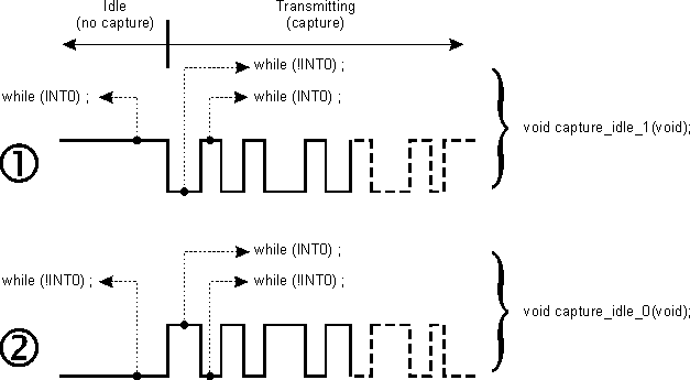
I wonder why i have to capture_idle_1 then get the result when Switch is press, please can you explain to me?
I hope this illustration can give you a clear situation
84_1169371981.gif


what you mean measure the idle voltage IT0, how to measure IT0, is it measure the INT0 pin without connecting Receiver Signal? If initial is Hi then we select capture_idle_1?
If our code select capture_idle_0, the result all the time is the same.
Use voltmeter to measure the voltage at INT0 pin when no key pressed, the '0' or '1' of INT0 at that condition determine whether you need time_idle-0 or time_idle_1.

Finally the graph comeout with standard pattern already ha.. But what we can know from the graph?
We don't need graph, but the number (periode of 'Space'/'mark'). Each key has it own unique 'Space'/'mark' number, it is the what we recoqnize which is the key pressed.

Please re-capturing the 'Space'/'mark' number of each key, and send itu to me.
(do it once for each key)
 

    Help

    Points: 2
    Helpful Answer Positive Rating
Hi,

Thank for your good explanation. It very helpfull for me.

What your mean re-capture the 'Space'/'mark' number of each key?
I already done it. Is it any problem in Graph2?
- Test1 and Test2 in Blue color graph is for Switch 1.
- Test3 and Test4 in Green color graph is for Switch 2.
- Test5 and Test6 in Yellow color graph is for Switch 3.

I capture 2 times for each key/Switch for us to do comparison.
If wan to re-capature the 3 key again, please let me know again. I will like to do it again.

Thank You.
 

Some question:
1. You use idle_1, it mean when no key pressed the voltage at INT0 is '1'. But why there is idel_1 no data graph? Does it mean without any key pressed there are still a pulses stream on OUT pin?
At this case I think you have to use osciloscope to make sure
2. What is the meaning of CYCLE (blue bar)?

Beside the graph, would you like to send the raw data too?
 

    Help

    Points: 2
    Helpful Answer Positive Rating
Status
Not open for further replies.

Similar threads

Part and Inventory Search

Welcome to EDABoard.com

Sponsor

Back
Top