Continue to Site

Welcome to EDAboard.com

Welcome to our site! EDAboard.com is an international Electronics Discussion Forum focused on EDA software, circuits, schematics, books, theory, papers, asic, pld, 8051, DSP, Network, RF, Analog Design, PCB, Service Manuals... and a whole lot more! To participate you need to register. Registration is free. Click here to register now.

8 channel differential audio mixer

Status
Not open for further replies.
chnaged plan, went for PGA2500 digitally controlled preamps. 10db - 65db gain..


Hi Frank , thanks for your comment :) makes total sence you don't want to have two faders per channel !! did'nt think of that one at all !!!

however, since i'm doing the fading digitaly in the dac I wont have that issue..

so, do I need to use 4 ic's (That 1280's) for the 8 channels to mix down to one single ended, then 8 resistor dividers + another OPAMP to recover level? or just the one IC with 16 devider resistors and a balanced output something like schematic i posted earlier?

I'm thinking, keep the signal balanced all the way through, becasue I can !! there will be a lot of other noisey stuff going on in the project so I'm hoping it might help with noise / interfearnce in the design to avoid single ended if I can..

I just ordered some OPA1632's for mic preamps for 8 channel differential ADC chip CS5368. the ADC needs 5Vpp input diferential, a bit less than the That 1510 / 1570 pre amps output. I guess I could have trimmed 1510 or 1570's back to 5Vpp but the OPA1632 just seamed to be made for the job.

well , i'll wire them up and hope i dont see a puff of smoke :) I'm hoping I can use my volt meter to see the Vpp outputs +/- peek with music or something to check before I blow anything up.. dont have either a sinal gen. or an oscillioscope :(

ok, i'm off to learn how to make 48v phantom power and preamp cuircit protection / rf choke on the inputs etc..ahhh!!! :bsdetector:
 

The common mode interference will travel through the whole mixer and reduce the dynamic range of it. Any error in the tracking of the faders or ADCs or the gain from side to side will reduce the CMRR and hence put the interference directly on one line or the other. Most ICs have better then 70 dBs power supply ripple rejection, I can not see any advantage of a fully differential amplifier.
Frank
 

interesting ! so why do they make ADC's and DAC's with differential IO ?

I don't have faders in my design, unless you mean the attenuators internal to the DAC and the PGA2500 preamp / gain controllers I've ordered...

Inputs / outputs of mixer will be differential, long cable runs. I thought differential signals had more voltage swing and therefore more dynamic range?
If there's no advantage I should order single ended ADC and DAC next time :) for now I'm doing everything differential if I can..

Do you know of a digitally controlled differential IO fader I could use as a mater volume control ? something similar to the PGA2500?


The common mode interference will travel through the whole mixer and reduce the dynamic range of it. Any error in the tracking of the faders or ADCs or the gain from side to side will reduce the CMRR and hence put the interference directly on one line or the other. Most ICs have better then 70 dBs power supply ripple rejection, I can not see any advantage of a fully differential amplifier.
Frank
 

This should have occurred to me earlier...

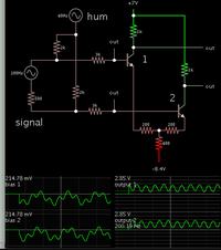
The first stage of an op amp is a differential amplifier. You make it from two transistors arranged as a long-tail pair. Take output from each collector leg.


The incoming signal is differential mode. Notice the 60-cycle hum is common mode (the kind that would intrude into a long run of wiring).

Practically all of the hum gets rejected. This is by benefit of the long-tail pair.

The signal is clean from the two outputs, in differential mode.

- - - Updated - - -

The supply is dual-polarity because it creates an easy way to bias the transistors. If you want to have a single supply for this circuit, it will be necessary to add biasing networks.
 

Hi Chuckey, I'll have two DACs running in parrallel sharing the same I2S source ( same clock ) even so , yes , maybe they could be fractionally out of phase ? I don't know ! do you happen to know if balanced audio CMR would cancel out audio that is slightly out of phase? still trying to work out why they bother making ADC's and DAC's with differntial IO if CMR kills off any dynamic range.. or you mean just in terms of me doubling up the DACs to achieve balance mixer Left / Right on each output channel ?

Also , Thanks BradtheRAD, yes I think I see simalar schematics for balanced audio IO opamps in the THAT opamp datasheets..

I am tempted to try to make Voltage controlled Attenuators for the 8 - 1 mix stages.. that way I can get the microcontroller to controll volume controll with PWM voltage.. NOT allowed to discuss this in this section of the forum.. ( Microcrontroller ileagle here :) ! )

anyway, building the PGA2500 preamps with phantom power protection and RF protection next with the 8 channel ADC. at least from ADC to DAC I can just hook up DSD or I2S lines. I'm keeping the whole thing modular so if one piece of the jigsaw is rubbish I can junk it and try something else.

and /or possibly junk the whole lot and go single ended if Chucky is correct and theres NO dynamic range because of CMR!!!

I herd some people saying the PGA2500 arn't as good as the THAT preamps since they dont have as much voltage swing, only +/- 2.5vpp I think.. but the ADC requires a maximum of +/-2.5vpp input, so would only have to atennuate the better preamps back down !! not sure there would be any point..


The common mode interference will travel through the whole mixer and reduce the dynamic range of it. Any error in the tracking of the faders or ADCs or the gain from side to side will reduce the CMRR and hence put the interference directly on one line or the other. Most ICs have better then 70 dBs power supply ripple rejection, I can not see any advantage of a fully differential amplifier.
Frank
 

I herd some people saying the PGA2500 arn't as good as the THAT preamps since they dont have as much voltage swing, only +/- 2.5vpp I think.. but the ADC requires a maximum of +/-2.5vpp input, so would only have to atennuate the better preamps back down !! not sure there would be any point..

In a usual mixing deck, a channel amplifier has considerable overload margin above the nominal full level output voltage. Power amplifier sensitivity is e.g. 1.4 Vrms, maximal undistorted channel output is e.g. 5 - 8 Vrms. Without this margin, you run at risk to overload a channel before the sum with any level setting below 0 dB. Should be obvious for anyone who ever worked in the sound reproduction field, either studio or stage.
 

ADC has maximum input voltage of 6vpp, 5vpp nominal with a dynamic range of 111db.

In a usual mixing deck, a channel amplifier has considerable overload margin above the nominal full level output voltage. Power amplifier sensitivity is e.g. 1.4 Vrms, maximal undistorted channel output is e.g. 5 - 8 Vrms. Without this margin, you run at risk to overload a channel before the sum with any level setting below 0 dB. Should be obvious for anyone who ever worked in the sound reproduction field, either studio or stage.
 

"interesting ! so why do they make ADC's and DAC's with differential IO ? "
ADC = analogue to digital convertor, differential input is what you want, differential O/P in digital, inverted code? or negative numbers?
DAC digital to analogue convertor, Differential I/P?, what sort of inverted digital input could be used?. Differential O/P is what you need to drive long analogue line.
If you are doing your fading " digitally" then I doubt if clock delays will will impair the balance of the audio or the CMRR. But the fact remains that if you have a bad input lead with 100mV of mains hum on it and 10mV of microphone sound then your system will be handling the mains hum and some where along the chain it would be good to remove it, the earlier the better. So using a good differential input amp with low noise, will "kill" the hum component and raise the signal level to 200mV or more. Taking your philosophy to its extreme, you will have a leg A input running right through your processing to become a leg A output, and the same for the leg B complete with the mains hum.
Frank
 

Status
Not open for further replies.

Similar threads

Part and Inventory Search

Welcome to EDABoard.com

Sponsor

Back
Top