Continue to Site

Welcome to EDAboard.com

Welcome to our site! EDAboard.com is an international Electronics Discussion Forum focused on EDA software, circuits, schematics, books, theory, papers, asic, pld, 8051, DSP, Network, RF, Analog Design, PCB, Service Manuals... and a whole lot more! To participate you need to register. Registration is free. Click here to register now.

DC motor H bridge current waveform

anotherbrick

Full Member level 4
Full Member level 4
Joined
Jan 10, 2009
Messages
222
Helped
1
Reputation
2
Reaction score
1
Trophy points
1,298
Location
Istanbul , Turkey
Activity points
3,190
hi dear forum members

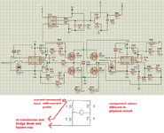
my question in the picture

thank you
current.jpg
 
thank you , diodes resistors caps are place holder in schematic real names and values different in physical circuit

schematic.png
 

Attachments

  • schematic.png
    schematic.png
    58.4 KB · Views: 101
Last edited:
you are seeing the current flowing into the electro across the fets, when they turn off motor current flows into electro - and source current still flows into electro - but reducing . . . .
 
you are seeing the current flowing into the electro across the fets, when they turn off motor current flows into electro - and source current still flows into electro - but reducing . . . .
If by “electro” you mean capacitor, then I agree. Which is why I asked to see a schematic to begin with…
 
Move the current probe so it only measures the current going to/from the MOSFETs.
I think that will be less confusing.
As you expect in post #1, when switching off MOSFETs 1 and 4, the current goes in MOSFETs 2 and 3 (body diode),
so the current to/from the MOSFETs will change polarity.
 
If - in the real world - you had the electro on the LHS of the current probe in your sketch above, rather than across the H bridge ( where it is but you omitted it from your sketch ) then you would see your expected waveforms.
 
thank you for all the answers,

I opened this discussion becouse the high side mosfets get warm when the average current is above 10 Amps,

I need to run this driver at 30 Amps without problem

why the high side gets warm ? ( low side is OK )

how to prevent this ? is my driving pattern wrong ?

( my mosfet STP100NF04 with 500 ns dead time - 10 Ohm forward gate resistor 3.3 Ohm backward resistor)

thank you
 
Hi,

I opened this discussion becouse the high side mosfets get warm
Sorry, but I can´t find anything about getting warm in the initial post.

***
And it´s too stressful for me to find out which information belongs to which and where can I find the other or the true part values...

like:
* "my question in the picture"
* "real names and values different in physical circuit"
* Transoistor 1 of sketch is Q5 on the schematic
* you show two patterns .. but only use one of them
" you say "current measured here" but indeed this is not true...

It´s a mess of contradicting informations.

Klaus
 
AND, there’s 100K resistors in series with the gate. That’s waaaaay wrong.
Scroll 10 times up, ten times down, read everything forward and back then maybe you get the information in post#10 ... but these still is far form complete informations.

I was about to write 4 posts where each post only holds a part of true and the other part of wrong informations for the OP to imagine how it feels for us.

Klaus
I don't have time for this.
 
Yes - a lot of oversights in the shown schematic, c17 & c19 should be larger than 18pF, try 470nF

and the 1o0k gate resistors are way too high, try 33 ohm turn on and 10 ohm turn off . . . .

@anotherbrick

R45, R50 should be 1 ohm.
 
I am sorry for taking your time,
I am working on this project for long time
my problem was this, The Mos getting hot under load and in the end breaking down

first I drive the mosfets like the pattern 1 in the first post - this time the low side mos gets hot and break down
then I drive the mosfets pattern 2 in the first post - this time high side mos gets hot - it didnot break down yet becouse I am afraid to load more and for long time

In the first post I didnot mentioned the gettting hot I am sorry for this ( but I thought the current waveform and driving pattern was the reason of getting hot of Mosfets )

I drive with 12Amps source current in tests - but I need to load the driver with at least 30 Amps while in operation ( accu wheelchair )

the values of the components in the schematic is wrong becouse the components are for place holder -the real values are in the picture

I am sorry If I cannot express myself well , this is my best english

I placed mosfets on aluminium plates 6 x 8 x 0.5 cm seperate for high and low side

thank you - I will change R45 R50 to 1 Ohm

schematic values.png


gates.jpg


circuit motor.jpg
 
I am sorry If I cannot express myself well , this is my best english
This has nothing to do with language, this has to do with presenting accurate information instead of showing us arbitrary numbers and forcing us to question you repeatedly until we get the “right” information.. A 100K resistor is the same in every language.
 

LaTeX Commands Quick-Menu:

Part and Inventory Search

Welcome to EDABoard.com

Sponsor

Back
Top