Continue to Site

Welcome to EDAboard.com

Welcome to our site! EDAboard.com is an international Electronics Discussion Forum focused on EDA software, circuits, schematics, books, theory, papers, asic, pld, 8051, DSP, Network, RF, Analog Design, PCB, Service Manuals... and a whole lot more! To participate you need to register. Registration is free. Click here to register now.

+40V 0v -40v / 10A SMPS For Power Amplifier

Status
Not open for further replies.
Hi Deepone
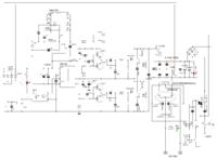
greetings and thanks for replying i try it as i am learning and rc snubber across collector to emitter across IGBT 12ohms in series with 4700pf or 470 pf i use 1kv one regards
andrew lebon

- - - Updated - - -

Hi Deepone
greetings and thanks for replying i try it as i am learning and rc snubber across collector to emitter across IGBT 12ohms in series with 4700pf or 470 pf i use 1kv one regards
andrew lebon
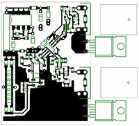
 

Much possible to avoid use these RC chains and having left only TVS, because this is not welding device. Or possible use RCD chain instead of RC (less resistor heating, more efficiency). Its capacity is suitable define with oscilloscope on size and form of surge spikes on IGBT collector (i use 4700pF).
In any event if level of the hindrances great, that RC or RCD chains is simmer and will not help, but in normal mode they relieve a IGBT life.
 
Hi Deepone
greetings any overcurrent protection schematic for this wonderful smps which you can share
warm regards
andrew lebon
 

Greetings, Andrew Lebon.
For overcurrent protection possible take off oscillator by shorting pins 3&4. But this scheme of protection is tested by me on small power only.

Or can be better use thyristor instead of TL431

also possible get not bad results with p-n fets assembly (like irf7309) for gate driving.
 
Last edited:
jestin,
you can use sg3525
1 power the sg3525 circuit from an isolated power supply
2 for driving the mosfets you have to use a driver like ir2110
3 mosfets have to be changed for 900v rating
4 feed back voltage should be isolated
 
Hi DeepOne
greetings just want to ask you if one more pair of IRF460 can be added after totem drivers to increase power is it possible
warm regards
andrew lebon
 

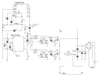
Hi. May be this could look as that scheme

______________________________________________________________
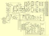
apropos here is else 200W scheme (from https://radiokot.ru/circuit/power/supply/33/)
may be useful for someone
 
Last edited:
Hi DeepOne
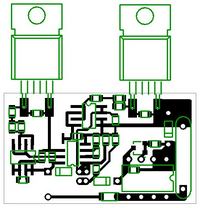
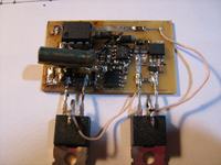
greetings thanks for post 48# added one more pair and increased load smps is working will post pics to show you my work
warm regards
andrew lebone
 

Hi Deepone
greetings and many many thanks for your help and guidance in making me complete this smps only regrets no protection
but its a great smps in 2 pairs IRF460 on resistve load halogen ac current drawn 9 amperes cant ask for more picture with my
dclass amps sound was very clear very satisfied with smps anything bigger you have for me to make viper ic is working i used VIPER22A
warm regards
andrew lebon
 

Attachments

  • DSCN3787.jpg
    DSCN3787.jpg
    2.6 MB · Views: 170
  • DSCN3789.jpg
    DSCN3789.jpg
    2.5 MB · Views: 196
  • DSCN3806.jpg
    DSCN3806.jpg
    259.6 KB · Views: 160

hello andrew and deepone
can i use 15v seprate supply for 2153?
what advantage of viper ic
 

Hi Stronghold6
greetings i used VIPER22A EASY TO USE AND circuit is more compact
warm regards
andrew lebon

- - - Updated - - -

Hi Deepone
greetings i am going to try your message from #44 please can you give details of current sensing transformer core ans swg wire details
i have yellow core from pc supply OD22MM ID 14 MM H 7MM is it ok to use
warm regards
andrew lebon
 

Hi Stronghold, Andrew Lebon.
can i use 15v seprate supply for 2153?
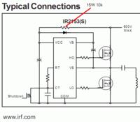
yes, of course. Possible even use simply 15W resistor like that as it is written in datasheet (with external 15V zener on ir2153 Vcc).
yellow core from pc supply OD22MM ID 14 MM H 7MM is it ok to use
no, yellow cores is only for DC. For high freq. AC it is need ferrite cores like №87 material.
About current transformers calculation -
**broken link removed**
detex audio say your smps is good
it is not my smps, only my version of this. )
 

Hi Andrew Lebon ,
1 what is maximum output power you have tested with the smps
2 Which circuit did you use
 
Last edited:

Hi Deepone
greetings tried both ocp circuits when i use TL431 and opto 817 smps does not come on when i use 555 ocp smps comes on but ocp not working
please any tips
warm regards
andrew lebon
 

Attachments

  • DSCN3811.JPG
    DSCN3811.JPG
    5.2 MB · Views: 174
  • ocp.JPG
    ocp.JPG
    85.7 KB · Views: 178

greetings Andrew Lebon
TL431 and opto 817 smps does not come on
Well, probably this signifies that optotransistor is open or perforated. To understand why it is possible to walk on scheme with voltmeter. Of course it is necessary disconnect power part from +310VDC for time of the testing. Apropos better use thyristor (like bt136) instead of TL431. Since if thyristor is opened that is latched.
when i use 555 ocp smps comes on but ocp not working
about this me not known nothing ).
 

Status
Not open for further replies.

Similar threads

Part and Inventory Search

Welcome to EDABoard.com

Sponsor

Back
Top