Continue to Site

Welcome to EDAboard.com

Welcome to our site! EDAboard.com is an international Electronics Discussion Forum focused on EDA software, circuits, schematics, books, theory, papers, asic, pld, 8051, DSP, Network, RF, Analog Design, PCB, Service Manuals... and a whole lot more! To participate you need to register. Registration is free. Click here to register now.

[SOLVED] ATMEGA32 Arduino library osccilator problem

Status
Not open for further replies.

johnny78

Full Member level 5
Full Member level 5
Joined
Jun 28, 2017
Messages
270
Helped
1
Reputation
2
Reaction score
5
Trophy points
1,298
Activity points
3,462
hi guys

i need to use the ATMEGA32 for a project but have a problem with Arduino library

i've downloaded this library & it works But the prblem is i have selected (External 16Mhz) as a clock source
& used the blink example to test the chip but the delay is 10x slower
so it blinks almost every 10 seconds instead of 1s
i have removed the crystal but it keeps working
so even the external source is using the internal oscillator

https://github.com/MCUdude/MightyCore

any suggested library or idea will be great or if you have a solution for this issue

thanks
Johnny


or USBasp +

Also google "USBasp atmega32"


Regards, Dana.
 

    johnny78

    Points: 2
    Helpful Answer Positive Rating


or USBasp +

Also google "USBasp atmega32"


Regards, Dana.
thanks But i have already programmed the Chip with Arduino IDE or Atmel studio

Johnny
--- Updated ---

Here is a link to an AVR fuse calculator:

https://eleccelerator.com/fusecalc/fusecalc.php?chip=atmega328p

The clock source is set by fuses.

The fuses can be checked and written with avrdude and an external programmer.

hi
there is no 16Mhz oscillator in the list
there is only (EXT. crystal/resonator HIGH Freq
or there is something wrong ?

Johnny
 
Last edited:

Here is a link to an AVR fuse calculator:

https://eleccelerator.com/fusecalc/fusecalc.php?chip=atmega328p

The clock source is set by fuses.

The fuses can be checked and written with avrdude and an external programmer.
hi
i have tried to set the fuses with Atmel Studio & yes the LOW.SUT_CKSEL = Int RC osc 1 Mhz
But how to select 16Mhz crystal ?
the only available selections is ext Crystal/Resonator HIGH Freq & the difference is the start-up time
its the same as the fuse calculator you have sent
i didnt understand how to select the right Crystal

thanks
Johnny
--- Updated ---

hi
i have tried to set the fuses with Atmel Studio & yes the LOW.SUT_CKSEL = Int RC osc 1 Mhz
But how to select 16Mhz crystal ?
the only available selections is ext Crystal/Resonator HIGH Freq & the difference is the start-up time
its the same as the fuse calculator you have sent
i didnt understand how to select the right Crystal

thanks
Johnny
i was checking the Datasheet but i couldnt find anything about HIGH Freq oscillator
im not sure of the Datasheet i have

can i set any HIGH Freq oscillator ?
 
Last edited:

Here is what I show for fuse bits -


CKOP settings ?


Regards, Dana.
 

For a 16 MHz crystal, select one of the "Ext. Crystal/Resonator High Freq" clock settings in the fuse calculator.
They don't specify the clock frequency, but have various start times to let the crystal resonator stabilize at start-up. These are setting the CKSEL and SUT fuse bits. Check the data sheet for more info on these.

If you look in the boards.txt file of your MightyCore software, you should see fuse values listed.
You can plug these into the fuse calculator and see what values they are setting. the boards.txt
also shows an f_cpu that they are using.

This is the listing they show in boards.txt for the atmega32 settings for running at 16 Mhz:

# Clock frequencies - This is the second part of the low fuse bit concatenation
32.menu.clock.16MHz_external=External 16 MHz
32.menu.clock.16MHz_external.upload.speed=115200
32.menu.clock.16MHz_external.bootloader.sut_cksel_bits=111111
32.menu.clock.16MHz_external.bootloader.ckopt_bit=0
32.menu.clock.16MHz_external.build.f_cpu=16000000L
 
Last edited:

Here is what I show for fuse bits -


CKOP settings ?


Regards, Dana.
its very confusing method & all the documents i read about this issue was not clear & its from single source i guess

anyway i have tried Ext Crystla/resonator Startup time 16k ck 64ms
& the chip cant communicate with the programmer any more
but when i touch the wires to the crystal the blink sketch works so slowly

i have built along time ago an HV programmer for the atmega328 i hope it can reset the fuses of the atmega32
or if u have another method
thanks

Johnny
--- Updated ---

For a 16 MHz crystal, select one of the "Ext. Crystal/Resonator High Freq" clock settings in the fuse calculator.
They don't specify the clock frequency, but have various start times to let the crystal resonator stabilize at start-up. These are setting the CKSEL and SUT fuse bits. Check the data sheet for more info on these. Any of the "Ext.Crystal/Resonator High Freq" settings will probably work OK.

If you look in the boards.txt file of your MightyCore software, you should see fuse values listed.
You can plug these into the fuse calculator and see what values they are setting. the boards.txt
also shows an f_cpu that they are using.
i have choosen the last option of the list in Atmel Sudio 7 Clock source
Ext crystal/resonator HIGH/resonator Start up time a6k ck + 64ms.
& connected the crystal but the blink sketch stopped working.
& cant connect to Atmel studio anymore

any suggestions?

Johnny
 
Last edited:

You are perhaps confusing the meaning of the External Oscillator with the External Crystal setting. With the external oscillator - which is likely your case - you need an external active circuit, not just connecting a crystal there. In addition, depending on the ATMega microcontroller ( I don't know yours, ATMEGA32 ) not all programmers will remove this fuse configuration with the ISP bus.
 

You are perhaps confusing the meaning of the External Oscillator with the External Crystal setting. With the external oscillator - which is likely your case - you need an external active circuit, not just connecting a crystal there. In addition, depending on the ATMega microcontroller ( I don't know yours, ATMEGA32 ) not all programmers will remove this fuse configuration with the ISP bus.
no im using external crystal not external oscillator & now when i touch the crystal pins the led blinks slowly i dont know how my hand generates some oscillation

let me tell you what i did exactly :
my blink sketch was running slowly so when opened the hex file in Atmel Studio the oscillator was the default for ATMEGA32 as i read its 1Mhz internal oscillator
i have tried to change it to 8Mhz internal & the led runs faster then not any document mentioned about secting 16Mhz external crystal So i thought its all the High freq crystal options are the same so i've choosen the last option
i dont know why its not this clear how to set external 16Mhx crystal?

if i was mistaken & choose the external oscillator how to guess what speed of pulse i need to generate to make it responce again to the ISP programmer ?
so i can use another MCU to generate the pulse

Johnny
 
Last edited:

im using external crystal not external oscillator & now when i touch the crystal pins the led blinks slowly

Your finger is just injecting ambient noise into the microcontroller's clock input pins, nothing else.

By the way, have a look at the technical sheet and you will see that once the fuse bit for external oscillator has been programmed, it will be necessary to carry out an annoying procedure to recover it, or better, just replace the stuck microcontroller by another one, and from now on review carefully the firmware downloading procedure.
ok after reading in all sections in Datasheet it was not clear how to set the 16Mhz crystal
would you please guide me to where i can find this info
 

Is touching pins with finger adding enough C to make xtal oscillator run ?

1640722474456.png


The layout "tight" because of the circulating currents and stray L considerations ?


Regards, Dana.
 

Hi,

With AVRs you need to program the firmware and the fuses separately.
Be sure this is done properly.

Klaus
 

Commonly the ambient noise coming from our finger is mains hum, which our bodies pick up simply being near house wiring. The voltage is on the order of 1V AC (as seen when I touch my finger to the oscilloscope probe).

It's hard to be sure which signal is detected and processed by your device... whether it's the 50/60 Hz hum, or whether the mains hum instigates the oscillator circuit to go into action during the time your finger touches it.
 

watch this video & keep an eye on my fingers as they get closer to the crystal wire it blinks faster
--- Updated ---

Hi,

With AVRs you need to program the firmware and the fuses separately.
Be sure this is done properly.

Klaus
i have laerned that from the previous post about ATMEGA Locking

Johnny
--- Updated ---

Is touching pins with finger adding enough C to make xtal oscillator run ?
watch the video i uploaded please
The layout "tight" because of the circulating currents and stray L considerations ?
what you mean ?
--- Updated ---

For a 16 MHz crystal, select one of the "Ext. Crystal/Resonator High Freq" clock settings in the fuse calculator.
They don't specify the clock frequency, but have various start times to let the crystal resonator stabilize at start-up. These are setting the CKSEL and SUT fuse bits. Check the data sheet for more info on these.

If you look in the boards.txt file of your MightyCore software, you should see fuse values listed.
You can plug these into the fuse calculator and see what values they are setting. the boards.txt
also shows an f_cpu that they are using.

This is the listing they show in boards.txt for the atmega32 settings for running at 16 Mhz:

# Clock frequencies - This is the second part of the low fuse bit concatenation
32.menu.clock.16MHz_external=External 16 MHz
32.menu.clock.16MHz_external.upload.speed=115200
32.menu.clock.16MHz_external.bootloader.sut_cksel_bits=111111
32.menu.clock.16MHz_external.bootloader.ckopt_bit=0
32.menu.clock.16MHz_external.build.f_cpu=16000000L
in my Arduino IDE the list includes ATMEGA32 16Mhz
But actually it keeps using the internal 1Mhz oscillator
thats why i have tried to set the oscillator manually

Johnny
 

Attachments

  • video-1640759190.mp4
    2.9 MB
Last edited:

That construction is absolutely horrible. It looks like you are connecting various crystals using long wires and a plug/socket. It will not work properly and it is a hardware problem, not exclusively software.

The rules around the oscillator crystal are that the tracks (= wires in your case) must be a short as possible. This doesn't only mean the connection to the crystal but the loading capacitors and the connection between their ground and the MCU VSS pin. You also need decouling capacitors across the supply pins to the MCU, they are not a nicety to make it more resilient against interference, they actually carry switching current, including the current through the oscillator circuit. Without them the oscillator either will not start or will be unstable.

Brian.
thanks brian
but this is a develpment board i use for more than 5 years & its just for test
yes i have various crystals on the board & i never had any problem with this development board since years
its easy & simple enough to test any small project i work on
i think always there is something unreasonable about electronics which cant be explained like when i touch the wires which generates clock to the MCU & spped up the blinking led as i touch more closely

anyway the chip is unusable anymore & its ok im not looking for solution to revive it now

Just help me to understand how to use the 16Mhz?
even in the AVR Fuse calculator or Atmel Studio its not clear
a good guide or explained tutorial will be good enough
thanks

Johnny
--- Updated ---

hi
i have removed the crystal wires & just connected 1 wire to Xtal1 pin 12 on the ATMEGA32
the led started to blink
the wire acts like an closck source Even without touching it
but when touching it goes faster

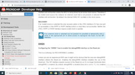
As i read in Microchip developer help documents i can apply an external clock to re program the chip via ISP
So maybe i can build a clock generator Code But
What possible clock speeds i need to test with ISP programming?

Johnny
 

Attachments

  • Screenshot (8).png
    Screenshot (8).png
    167.8 KB · Views: 190
Last edited:

What possible clock speeds i need to test with ISP programming?
The programmer software will dictate the speed, there are in general options available to set up at your choice.
 

Hi
but this is a develpment board i use for more than 5 years & its just for test
I agree with brian.
Lucky you that it works most of the time. But it's surely not reliable.

i think always there is something unreasonable about electronics which cant be explained
I don't agree. There always is a reason....

Some rules
* a fast ceramics capacitor at almost each supply pin of each IC.
* a signal is never a one way from A to B, one alwas has to consider the way back from B to A. It is a loop.
* for "switching signals" one has to think about "impedance". Thus thick and wide wires/traces do not improve signal quality. Short traces, small enclosed area in the "signal and return" loop is what counts.
* it's the "edge" that causes high frequency ... and ringing. Thus a 1Hz LED blink signal cuases the same ringing as a 100kHz PWM signal, it´s just multiplied with time.
* especially for not that experienced PCB layouters I recommend to use a GND plane. It reduces all the above mentioned problems.

In your case: to reduce the "loop area" --> just twist all (IN, OUT, GND) wires to the XTAL. It´s still not perfect, but much better regarding EMI, EMC and stray inductance.

Klaus
 

Status
Not open for further replies.

Similar threads

Part and Inventory Search

Welcome to EDABoard.com

Sponsor

Back
Top