horttanainen
Member level 2

- Joined
- Jul 18, 2020
- Messages
- 42
- Helped
- 0
- Reputation
- 0
- Reaction score
- 0
- Trophy points
- 6
- Location
- Helsinki, Finland
- Activity points
- 492
The problem:
The TV emits a high pitched noise when turned on. On the video the sound seems to come from the power supply board, but I am not sure.
I measured the resistance of both the horizontal and vertical deflection circuits and it seems that I have burned something in the horizontal deflection circuit.


Could you please help me debug this problem? I have never debugged electronics before and do not know where to start or how. I have an analogue oscilloscope, signal generator, and a multimeter available. I also have an assortment of electronics components but they are of low wattage rating.
Specs
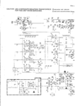
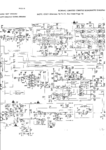
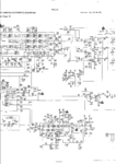
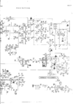
The TV in question is a Commodore 1084S-P monitor

What happened:
I was turning my Commodore 1084S-P monitor into an oscillographic TV following this guide. This "hack" requires separating of horizontal and vertical deflection yoke driver cables from the TV circuit board, which I did as instructed. Having measured the resistance of both the vertical (13ohm) and horizontal (4ohm) deflection yokes, I connected the respective wires from the circuit board with sanbar resistors creating the so called "dummy coils". I tried to turn the TV on but got only a high pitched sound. The TV circuit board detected that there was something wrong with the deflectors and refused to power on. By reconnecting the horizontal deflection coil driver to the TV circuit I was able to get a horizontal line on the TV screen.
I concluded that somehow the horizontal dummy coil was not enough to fool the TV circuit. I measured the inductance of horizontal deflection coil (1800 microhenries) and wound an inductor of about the same inductance (2000 microhenries). By connecting this new "dummy coil" the TV turned on. I reconnected the vertical deflection driver cables back to the TV circuit to create a vertical line and turned the brightness control all the way down to avoid damaging the CRT. I was happy with this achievement for about two minutes, until the line started to get brighter and to "wobble". I quicly turned the TV off to prevent damage but upon restarting the TV just gave a high pitched whining sound. The horizontal dummy coil inductor was very hot. I forgot to measure its resistance (2ohm) and add a respective sandbar resistor!
The TV wont turn on. Not even when I reconnect the deflection yokes to the TV circuit. Instead a high pitched noise ensues.
Why I want to repair this TV
This is a hobby project and I am looking to get better at electronics. When I started this project I knew next to nothing about electronics. I think repairing this TV will be an excellent learning opportunity.
The TV emits a high pitched noise when turned on. On the video the sound seems to come from the power supply board, but I am not sure.
I measured the resistance of both the horizontal and vertical deflection circuits and it seems that I have burned something in the horizontal deflection circuit.
Could you please help me debug this problem? I have never debugged electronics before and do not know where to start or how. I have an analogue oscilloscope, signal generator, and a multimeter available. I also have an assortment of electronics components but they are of low wattage rating.
Specs
The TV in question is a Commodore 1084S-P monitor
What happened:
I was turning my Commodore 1084S-P monitor into an oscillographic TV following this guide. This "hack" requires separating of horizontal and vertical deflection yoke driver cables from the TV circuit board, which I did as instructed. Having measured the resistance of both the vertical (13ohm) and horizontal (4ohm) deflection yokes, I connected the respective wires from the circuit board with sanbar resistors creating the so called "dummy coils". I tried to turn the TV on but got only a high pitched sound. The TV circuit board detected that there was something wrong with the deflectors and refused to power on. By reconnecting the horizontal deflection coil driver to the TV circuit I was able to get a horizontal line on the TV screen.
I concluded that somehow the horizontal dummy coil was not enough to fool the TV circuit. I measured the inductance of horizontal deflection coil (1800 microhenries) and wound an inductor of about the same inductance (2000 microhenries). By connecting this new "dummy coil" the TV turned on. I reconnected the vertical deflection driver cables back to the TV circuit to create a vertical line and turned the brightness control all the way down to avoid damaging the CRT. I was happy with this achievement for about two minutes, until the line started to get brighter and to "wobble". I quicly turned the TV off to prevent damage but upon restarting the TV just gave a high pitched whining sound. The horizontal dummy coil inductor was very hot. I forgot to measure its resistance (2ohm) and add a respective sandbar resistor!
The TV wont turn on. Not even when I reconnect the deflection yokes to the TV circuit. Instead a high pitched noise ensues.
Why I want to repair this TV
This is a hobby project and I am looking to get better at electronics. When I started this project I knew next to nothing about electronics. I think repairing this TV will be an excellent learning opportunity.
Last edited:
