Karolina_1
Member level 3

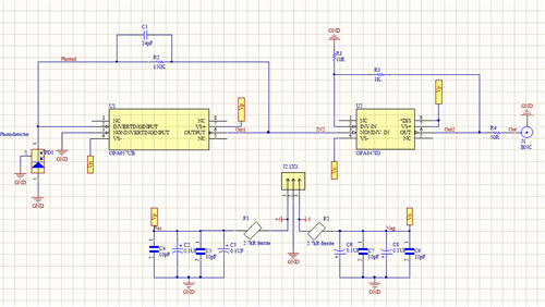
Hello Everyone? I have an oscillation issue on a photodiode trans-impedance amplifier whose simplified schematic I'm attaching in this thread. The design consists of a high gain / high bandwidth trans-impedance stage using a JFET Input OPA657 (SOT23-5 Package), followed with a voltage gain of 101V/V made with an OPA847 (SOT23-6 Package). All components used are SMD technology. Transimpedance stage works fine, OPA657 is functioning good, however, there is a high-frequency oscillation at the output of the OPA847. For that reason, I am only testing the OPA847 part(OPA657 is removed). I connected the signal generator to the non-inverting input of the OPA847. In tests, I am inputting 100mVpp, 50Hz signal. And I am using 40R and 1000R resistances (gain 21V/V) and measuring the voltage after 50R resistance.
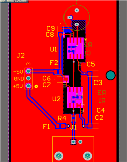
Opamp has 2 bypass capacitors on each supply pin (0402/10pF - Ceramic, 1206/100nF Tantalum) and ferrite bead on each supply pin of the opamps (Murata BLM21BD272SH1L). All of them are very close to the pins. I followed all the indications on the application notes of each opamp to make the entire PCB. The implementation was made in a 2 layer, FR4 PCB.
The circuit oscillates around 20 MHz. Here are the things I tested to figure out what kind of problem I have (without success):
1. Putting the 10uF Aluminium electrolytic capacitor.
2. Removing 0402/10pF - Ceramic cap and replacing them with 0603/0.1uF Ceramic cap.
3.Using different power supply.
4. Putting 10R resistance in series with both negative and positive power pins.
5. Changing different resistor combinations, so that gain>20V/V.
6. Replacing OPA847.
It's not an ambient pick-up when power off the high freq oscillation goes away.


