redreobingarden
Newbie level 3

Hello! I am an idiot when it comes to analog circuit design.
So, I have a sealed electronic enclosure that will be going underwater. I am designing a circuit board to do some stuff and communicate with a topside computer. I figured, well if I'm designing the circuit board, why not add a simple "leak sensor" based on the conductivity between two bare traces on the board.
This led to me trying to design a simple leak detector that will send a logic signal from 0 to 5 volts (the actual logic level 0 needs to be a voltage less than 1.0 and the logic high is a voltage higher 2.4v)
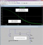
Essentially it needs to be something like this:

So I did some resistance measurement of water and I'm getting something around 100K - 300K ohms resistance value for two probes that are close to each other in water.
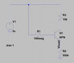
I figured I need to use a transistor and have the base resistor be the "leak sensor traces". I started playing around with a simple NPN transistor and did some calculations on what other resistor values I should use but I really have no idea what I'm doing.

Anyone have any pointers on how I should design this circuit?
Thanks!
-Paul
So, I have a sealed electronic enclosure that will be going underwater. I am designing a circuit board to do some stuff and communicate with a topside computer. I figured, well if I'm designing the circuit board, why not add a simple "leak sensor" based on the conductivity between two bare traces on the board.
This led to me trying to design a simple leak detector that will send a logic signal from 0 to 5 volts (the actual logic level 0 needs to be a voltage less than 1.0 and the logic high is a voltage higher 2.4v)
Essentially it needs to be something like this:

So I did some resistance measurement of water and I'm getting something around 100K - 300K ohms resistance value for two probes that are close to each other in water.
I figured I need to use a transistor and have the base resistor be the "leak sensor traces". I started playing around with a simple NPN transistor and did some calculations on what other resistor values I should use but I really have no idea what I'm doing.

Anyone have any pointers on how I should design this circuit?
Thanks!
-Paul


