Continue to Site

Welcome to EDAboard.com

Welcome to our site! EDAboard.com is an international Electronics Discussion Forum focused on EDA software, circuits, schematics, books, theory, papers, asic, pld, 8051, DSP, Network, RF, Analog Design, PCB, Service Manuals... and a whole lot more! To participate you need to register. Registration is free. Click here to register now.

[SOLVED] 3-digit Frequency Counter

Status
Not open for further replies.
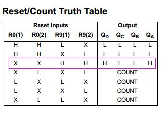
Now, first three are fine and same outputs as shown in the Truth table. But when I want to get count on the output then LEDs are all low for last four states.
see here what I did on the multisim
View attachment 89485

To get a count at the led's:

Pins 2,3,6,7,10 must go to ground.

Pulses go to pin 14.

Connect pin 1 & 12 (bit A out).

- - - Updated - - -

Now, first three are fine and same outputs as shown in the Truth table. But when I want to get count on the output then LEDs are all low for last four states.
see here what I did on the multisim
View attachment 89485

To get a count at the led's:

Pins 2,3,6,7,10 must go to ground.

Pulses go to pin 14.

Connect pin 1 & 12 (bit A out).
 

What exactly your project is about. Is to simulate in Multisim or make hardware or explain the theory behind? You have schematics already given.
 

@BradtheRad
Yes sir, I did it. I am trying other possible connections too.

- - - Updated - - -

@ALTERLINKS
It is to hard wire on the breadboard. But my lab teachers don't allow anyone to bring that hard wired circuit at home. So I thought, I should try it on any software first.
 

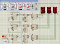
Here is counter for up to 999 Hz.
 

Attachments

  • 3 digit FC.rar
    13.9 KB · Views: 143

Congratulation to all the experts who are helping me. I have successfully constructed one part of the frequency counter in the lab today. Thank you all. Now in the next week (Monday) I will constructed second part and try to construct third part too.
I had headache today so much that's why I am replying this time.

@ALTERLINKS.
helped me so so much. But still confusion. How did you come with the idea to choose clock frequency 500mHz? :(
 

The unit of frequency is the hertz (Hz), named after the German physicist Heinrich Hertz: 1 Hz means that an event repeats once per second. A previous name for this unit was cycles per second.
For cyclical processes, such as rotation, oscillations, or waves, frequency is defined as a number of cycles per unit time.
As it is a frequency counter, it will count occurrences in unit time (1 second).
The period, usually denoted by T, is the length of time taken by one cycle, and is the reciprocal of the frequency f:
The unit for period is the second.
0.5 Hz is one second on and one second off ( 50% duty cycle).
Here period is 2 seconds but we are only interested in 1 second during which pulse is low. Its because 7490 comes out of reset state and starts counting during the time pulse is low. As it has counted for one second and now pulse is changes to high_state, it serves two purposes. 7490 is reset but just before that the count data on its output is latched into 74173 because its clk input is rising pulse triggered. Now no need for further timing. We can change duty cycle to reduce on_time. Frequency will also change because off_time is fixed for one second. Cycle repeats itself.
 

Hello.

I understand why we chose 500mHz just little. I will try some more experiments by changing this frequency may be i get idea about this.

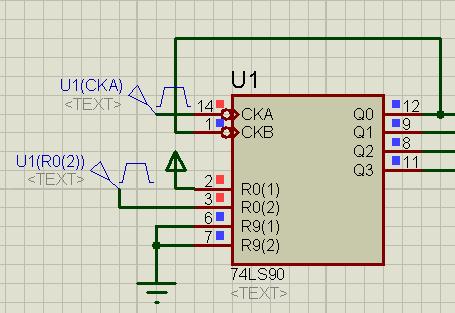
One more thing, you have grounded R91 and clock at R01. Why this is so?

Thank you sir
 

Hello teachers!

I want to know. Please pay attention to me too.

Thank you.
 

About R01 and R02. I was sleepy, i guess that i connected that way. I was following your circuit so it must be like that. These pins are similar otherwise, so simulation was correct.
.
In simulation, From 1KHz It starts from 0 again because it only shows three least significant digits. There is no overflow indicator.
Practically timebase hardware is required in addition to input pulse conditioning to make a functional gadget. Power supply also requires filter capacitors on ICs power pins.
Either R91 or R92 should be grounded otherwise only 9 will be on output. Simulator treats open pins as high. Practically grounding them may not be required as in your circuit.
4613476400_1366500703.jpg
 

Attachments

  • FC.rar
    14 KB · Views: 138
  • Like
Reactions: Eshal

    Eshal

    Points: 2
    Helpful Answer Positive Rating
Hello.

I understand why we chose 500mHz just little. I will try some more experiments by changing this frequency may be i get idea about this.

One more thing, you have grounded R91 and clock at R01. Why this is so?

Thank you sir

I wonder if you are referring to my post advising to ground pins 2, 3, 6, 7 of the 7490? I may have been mistaken, since that applies to a single digit. Contrariwise, you have multiple digits.

Ignore me, and instead consider the diagram at the link below.

https://www.devredeposu.com/wp-content/uploads/2012/12/Ekran-Alıntısı29-210x210.png
 

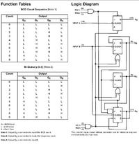
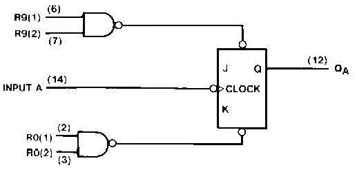
If you see internal diagram of the IC,

you will find there are 2 input nand gates for R01,R02 and R91,R92 which control JK flip-flop.
7878739600_1366606536.jpg

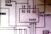
It is better to connect inputs to some logic level and not let them floating like in the original schematic.
6093194900_1366609233.jpg
.
9966076100_1366608657.jpg
 
  • Like
Reactions: Eshal

    Eshal

    Points: 2
    Helpful Answer Positive Rating
I understood it. Thank you very much. So easy wordings. Thank you all here. Thank you very much.
All teachers are very great and I am greatful that they helped me.
 

Dear Experts
I have also complete the same circuit. 4 digit frequency counter. which counts from 0 to 9999 Hz. now i want to count in MHz but with same circuit and the main point is this that only these 4 digit will used and count in MHz. i mean is this possible that this 4 digit frequency counter can count in Mhz. what is the circuit configuration?????

You want to divide the incoming signal by 1000. The easy way is by running your signal through divide-by-10 counter IC's.

The 7490 series is typical. Here's a link to a thread:

https://www.edaboard.com/threads/87879/

There will be a list of related threads at the bottom of that page.
 
can u send me the modified schematic. my teacher is saying that do not add new component just change the circuit configuration and your circuit will work for Mhz. but how i dont understand please send me the complete schematic. thank you so much for your reply.
 

As I explained in post #26, we were enabling count for 1sec so we got readout in Hz. It will be obvious that if we change clock to 5Hz, frequency will be divided by 10. If it is changed to 50Hz, a division of 1/100 will occur. At 500Hz clock, display will be in KHz.
 

What I understand,
We were counting in Hz so we use 500mHz.
If I want to count in KHz then I need to change clock frequency to 500Hz.
If I want to count in MHz then I need to change clock frequency to 500KHz.
If I want to count in GHz then I need to change clock frequency to 500MHz.
Right sir?
 

    V

    Points: 2
    Helpful Answer Positive Rating
What I understand,
We were counting in Hz so we use 500mHz.
If I want to count in KHz then I need to change clock frequency to 500Hz.
If I want to count in MHz then I need to change clock frequency to 500KHz.
If I want to count in GHz then I need to change clock frequency to 500MHz.
Right sir?

Yes, theoretically.

It all hinges on the ability of your counting circuit to count that fast. There will be some point where it will need a pre-scaler.
 

Status
Not open for further replies.

Part and Inventory Search

Welcome to EDABoard.com

Sponsor

Back
Top